By Melodie Yashar, A.M.ASCE, Calvin Glasgow, Bungane Mehlomakulu, Jason Ballard, Julian O. Salazar, Stephanie Mauer, and Sam Covey, P.E.
On June 25, four individuals entered a 1,700 sq ft, 3D-printed, closed habitat to begin a 378-day-long simulated mission on Mars. Following is the story of how this structure was created.
The journey to living and working on Mars has begun. In September 2020, ICON Technology Inc., a company developing 3D-printing technologies, was awarded a subcontract through Jacobs, a global engineering services firm, to deliver a 3D-printed structure dubbed Mars Dune Alpha. According to NASA’s website, Mars Dune Alpha is a “unique 3D-printed habitat designed to serve as an analog for one-year missions to the Martian surface.” These simulated missions support NASA’s Crew Health and Performance Exploration Analog program, known as CHAPEA.
The design phase for the habitat began in October 2020, printing and construction occurred in June 2021, and interior finish-out occurred in early 2022. And on June 25 of this year, the first four-person mission began. The second and third missions are slated for 2025 and 2026, according to NASA’s website on the project.
Data from the missions will be used to advance NASA standards relative to crew health and behavioral performance issues, habitability, and food-system requirements for future long-duration missions on the moon and Mars.
Habitat design
As a functional analog habitat, Mars Dune Alpha represents a major technological step forward. Future surface-exploration missions on the moon and Mars will leverage large-scale additive manufacturing (or 3D printing) with in situ resources to eliminate the need to launch large quantities of building materials from Earth, a process that is cost-prohibitive for the development of horizonal and vertical planetary infrastructure.
In addition to its cost-effectiveness, additive manufacturing can be deployed autonomously to erect various types of planetary structures prior to a crew’s arrival. Additionally, 3D printing affords great versatility for the construction of a wide range of structural geometries on demand. Because 3D printing has been identified by NASA as a candidate construction method for in situ construction of lunar and Martian habitats, CHAPEA was identified as a test bed and proving ground for how the technology might apply in the construction of an Earth-based, analog environment.
Site and building constraints
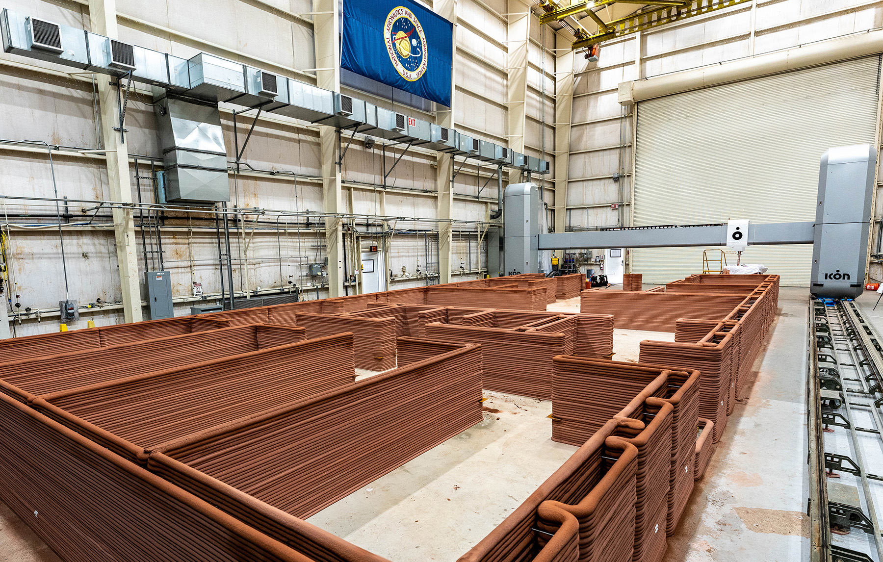
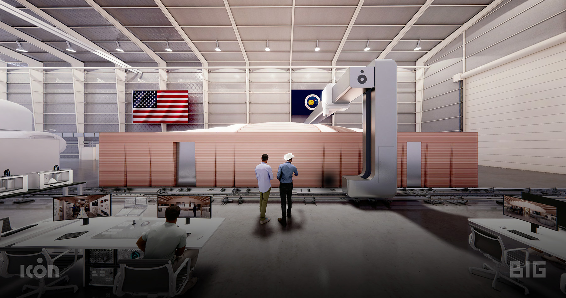
The structure, in the northwest side of Building 220 at the Johnson Space Center in Houston, was designed by architecture firm Bjarke Ingels Group with structural engineering by Fort Structures. NASA required a target area of roughly 60 ft by 28 ft for the overall structure, and it also dictated that the structure not exceed a maximum slab load of 500 pound-force per sq ft, which meant the habitat itself and its equipment and furnishings could not exceed a total weight of 750,000 lb. The habitat accommodates multiple paths of egress through B220.
NASA also designed a mock airlock, airlock node, and sandbox — for simulating extravehicular activities — adjacent to the habitat.
Printing the habitat
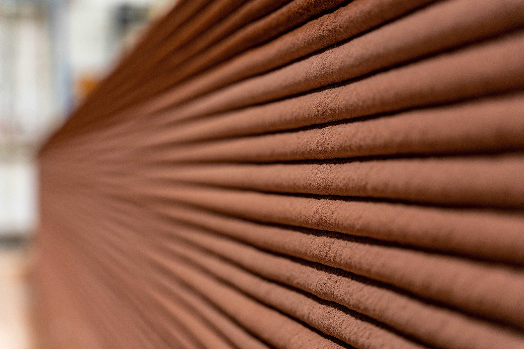
ICON deployed its Vulcan 3D-printing system to construct the habitat. The Vulcan is a gantry-style, robotic system engineered to print Lavacrete, a proprietary mortar-based concrete material. Dyes were incorporated into the normally gray-colored Lavacrete to simulate the reddish tones of Martian regolith. ICON’s material handling and mixing system, Magma, was located outside B220.
The Vulcan printer operates on rails that span the length of a structure. Once the printer rails were set, the Vulcan’s towers were erected on the rails followed by placement of the printer’s X-beam (electronic beam). The X-beam was attached to the towers, and all cabling and the concrete hose between Magma and the printer were installed and connected.
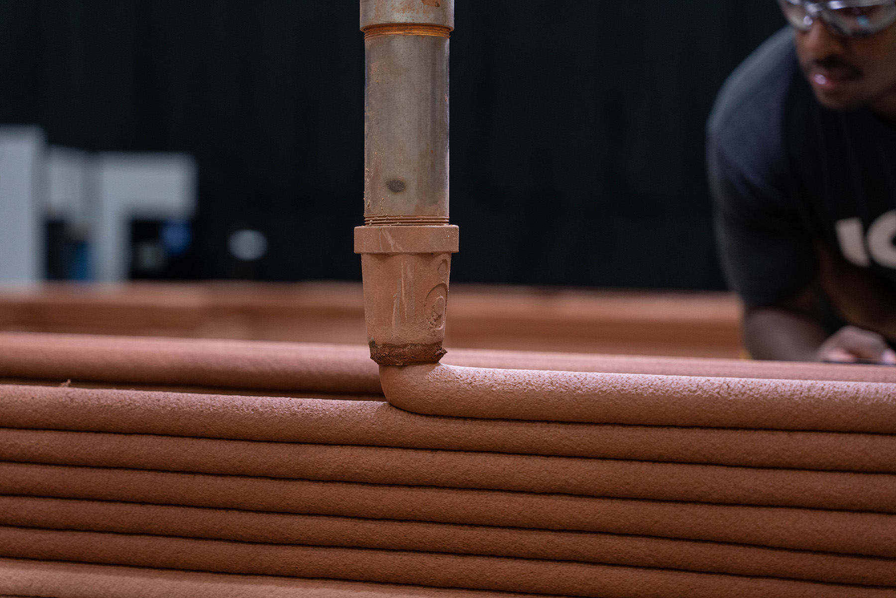
The next step was to calibrate the printer and perform a dry run (without any material extruded) of the print path to check that the code ran as required. After the material properties were tested, the printing procedure began with a team comprising a print captain, print operator, and a Magma operator along with associated support for quality control.
Habitat requirements
The list of must-haves for the habitat was lengthy. The layout of the structure synthesized NASA’s requirements for each of the functional habitat program areas by organizing the program areas (from south to north in plan) in a gradient of most private to most public. Defined by NASA and Jacobs prior to ICON’s involvement in the project, the design specified that the habitat be a single-story (deemed safter than multiple stories) 3D-printed structure, provide a minimum of 1,500 sq ft of living space, have a minimum interior ceiling height of 8 ft, and be a fully enclosed structure.
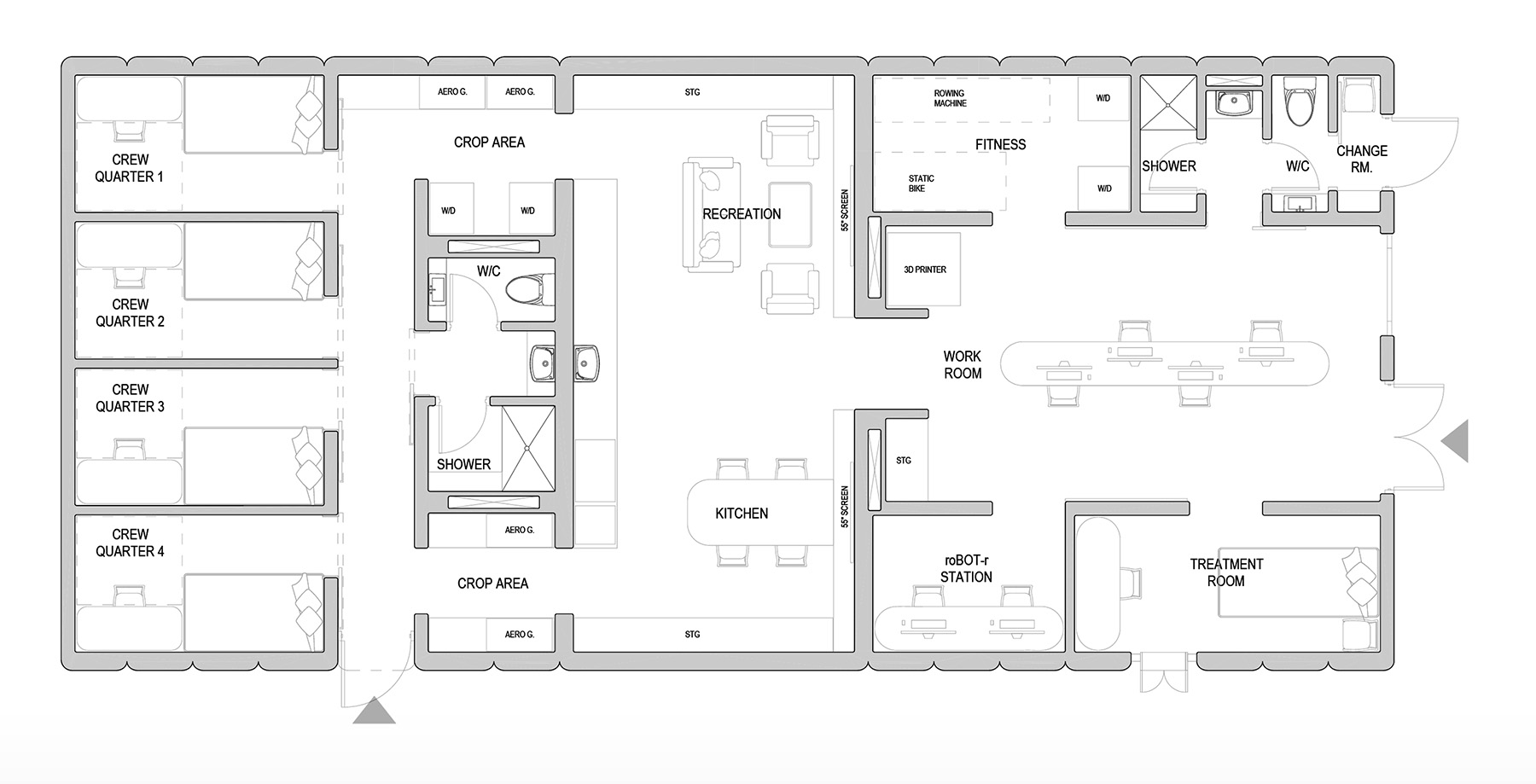
All utility connections were required to be on the west side of the habitat. Of the two exits required, one had to be on the north side of the habitat to accommodate the interface to the habitat airlock.
Crew members have their own quarters, all with adequate space for a single bed, personal storage (roughly 50-70 kg for clothing and 50 kg for personal equipment), and a chair and desk.
As its name implies, the leisure room includes a shared recreation and living space as well as a kitchen. Requirements for the kitchen include a sink and food preparation area, small refrigerator, storage capacity for food packages, and a food heater roughly the size of a medium-size microwave.
The crop growth area of the habitat — anticipated to be four large tray towers for aeroponic crop growth — is adjacent to the kitchen and near the trash disposal area.
For the crew’s physical well-being, NASA mandated two 8 ft by 4 ft (minimum) exercise areas: one for aerobic activities and the other for weightlifting. Additionally for the crew’s health, the design specified a private medical station with a treatment bed and an exterior wall that could accommodate a refrigerator (for storing medicine and biological samples) and an opening for the crew to pass these samples to the ground support team.
NASA requested bathrooms in two locations of the habitat: near the crew quarters and within the working area (closer to the airlock exit). The secondary bathroom in the work area presents an opportunity for NASA to collect data and develop solutions for bathroom needs as they might occur during extravehicular activities.
The design team also had to create an enclosed space (roughly 2.7 ft by 3 ft by 2.3 ft) for a ROBoT-r telerobotic machine intended to test crew performance during precision tasks. In the same room are a public affairs and outreach workstation, including a desk, chair, and camera for live-video public events or personal communications.
Finally, the habitat has a workroom that includes dedicated workstations for all four crew members, barn doors covered in dry-erase paint for writable and erasable surfaces, and space (about 80 in. by 40 in. by 40 in.) for a polymer-based 3D printer with increased air ventilation around it.
Architectural concept
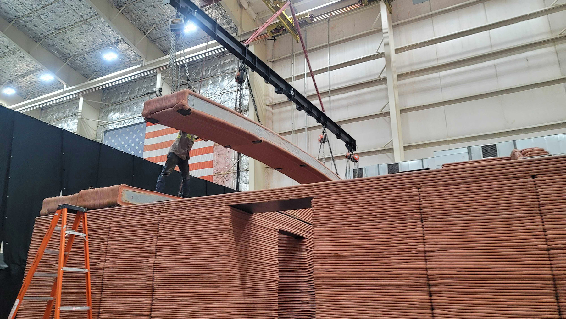
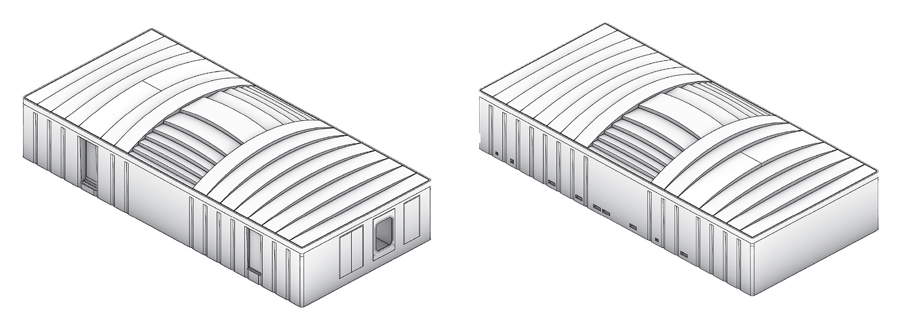
The design team devised a panelized roof that creates dynamic ceiling heights within the public/shared program areas of the habitat. The orientation of the ceiling panels differentiates the primary programs of the habitat.
Roof members were printed outside and then grouted, cured, lifted, and lowered into place using the overhead crane in B220. All the roof panel bond beams were grouted with embedded lifting points for rigging the panels to the overhead crane. The typical width of the roof panels that span north-south in plan is roughly 3 ft. In the center of the habitat (east-west in plan), the roof panels range from 1 ft to 4 ft in width.
The north facade features a pass-through to the habitat’s simulation node and airlock, double doors (intended to remain closed and nonoperational for the duration of the analog simulation), and emergency egress from the habitat’s secondary restroom. The east facade features a medical pass-through, a medical diagnostic window, and an additional egress door. The west facade contains openings for mechanical, electrical, and plumbing services into the habitat, which are covered by a catwalk.
The habitat’s heating, ventilation, and air-conditioning system maintains a temperature of 70-80 F, and an underfloor air-distribution system pushes air throughout the habitat. Air from the UFAD system is returned at high levels through chase walls within the 3D-printed walls. Return-air openings are cut into the tops of the walls.
The raised-access floor created for the UFAD system is also used as the primary electrical and low-voltage distribution system and sits 12 in. above the topping slab. In most of the habitat, the raised-access floor is removable concrete tile, while the restrooms have recessed concrete tiles with a waterproof membrane and ceramic tile floor finish.
The habitat also includes a fire protection system, smoke detectors, and carbon dioxide monitors. The sprinkler lines are mounted overhead throughout the habitat. Most lighting fixtures are suspended throughout the public program areas of the habitat, and the lighting is adjustable and controllable from inside and outside the habitat.
Additionally, there are 10 globe cameras placed around the habitat — except in bathrooms and crew quarters — for surveillance and monitoring by mission control.
Structure and wall system
Work crews constructed an 8 in. thick topping slab to adequately distribute the weight of the structure upon the existing slab. The finished floor of the habitat is 1 ft, 8 in. above the existing B220 finished floor. The typical wall thickness for interior and exterior load-bearing walls is 10 in., while the typical interior non-load-bearing wall thickness is 7.5 in. Some interior non-load-bearing walls of the habitat are 5 in. thick.
The habitat walls are not insulated because B220 is already a conditioned environment. Grouted structural cores are located at typical spans throughout the exterior wall. Steel lintels were introduced at the tops of door openings and span other access points within the printed wall.
The exterior walls of the habitat introduce folds within the print path that align with roof panel widths above them and that also function as control joints to mitigate cracking within the walls. Fully grouted low-bond beams were poured at exterior walls in addition to continuous bond beams poured at the tops of wall conditions.
Mars Dune Alpha has been designed and built to fulfill NASA’s mission requirements and the needs of the CHAPEA campaign. The habitat advances the viability of large-scale additive manufacturing technologies for the autonomous construction of surface structures in deep space by integrating Earth-brought interfaces and components and other utilities.
The habitat also demonstrates the successful creation of a fully enclosed 3D-printed structure that is the first of its kind to ever be employed for analog missions and research at NASA.
Maybe Mars really isn’t that far away.
Sidebar: Explore more
According to NASA, to make the Mars Dune Alpha experience as realistic as possible, crew members may participate in activities like simulated spacewalks using virtual reality, growing their own crops, preparing their own meals, performing maintenance duties, and doing other work related to the mission.

What’s more, this simulation will not be smooth sailing. They may find themselves short of supplies, experience equipment failure, and contend with significant workloads.
Read more about the Crew Health and Performance Exploration Analog program and the crew’s mission.
This article is based on the paper, “Mars Dune Alpha: A 3D-Printed Habitat by ICON/BIG for NASA’s Crew Health and Performance Exploration Analog (CHAPEA),” presented at the Earth & Space 2022 conference held April 25-28, 2022, in Denver.
Melodie Yashar, A.M.ASCE, is the vice president of building design and performance, Calvin Glasgow is a construction project manager, Bungane Mehlomakulu is the director of building science and building performance, and Jason Ballard is the CEO of ICON Technology Inc.. Julian O. Salazar is a senior architect at Bjarke Ingels Group (BIG). Stephanie Mauer (formerly a senior architect at BIG) is a design architect at SHAPE. Sam Covey, P.E., is a principal structural engineer for Fort Structures.
Project credits
Owner: NASA, Houston
Architect: Bjarke Ingels Group, New York City
3D fabrication and construction: ICON Technology Inc., Austin, Texas
Structural engineer: Fort Structures, Austin, Texas
This article first appeared in the September/October 2023 print issue of Civil Engineering as “Fit for Mars.”
Melodie Yashar, A.M.ASCE, was a guest on an ASCE Interchange Live called “Off-planet possibilities: The future of our built worlds.”