By Praveen K. Malhotra, Ph.D., P.E., M.ASCE
Anyone who has considered buying a Swiss watch knows the difference between water resistant and waterproof. Simply put, a water-resistant watch can withstand some contact with water, but a waterproof watch is practically impervious to water. Similarly, there is a difference between collapse resistant and collapse proof. A collapse-resistant structure can withstand most earthquakes, but a collapse-proof structure can withstand practically any earthquake and its aftershocks. This article explains why we must consider collapse-proof seismic design and how to achieve it.
Collapse-proof versus collapse-resistant design
Earthquakes are caused by the rupture of the brittle skin of the earth (crust) due to the movement of magma underneath. Neither the properties of the crust nor the velocity of magma is known with any certainty; therefore, the ground motions produced by earthquakes cannot be predicted with any certainty.
In the United States, future ground motions are predicted by the United States Geological Survey by using probabilistic analysis of recorded and inferred ground motions. According to the USGS, any intensity of ground shaking is possible at any given site. Higher-intensity shaking is less likely and lower-intensity shaking is more likely, but any intensity of shaking is technically possible. Without an upper limit on the intensity of ground shaking, engineers are forced to accept some risk of structural collapse.
This is a surprise to those who think that structures designed according to modern codes are collapse proof if not damage proof. Per ASCE 7, Minimum Design Loads and Associated Criteria for Buildings and Other Structures, ordinary structures should not collapse during the risk-targeted maximum considered earthquake ground motions predicted by the USGS. The mean return period of MCER ground motions is about 1,000 years in high-seismic areas and 2,500 years in low- to moderate-seismic areas.
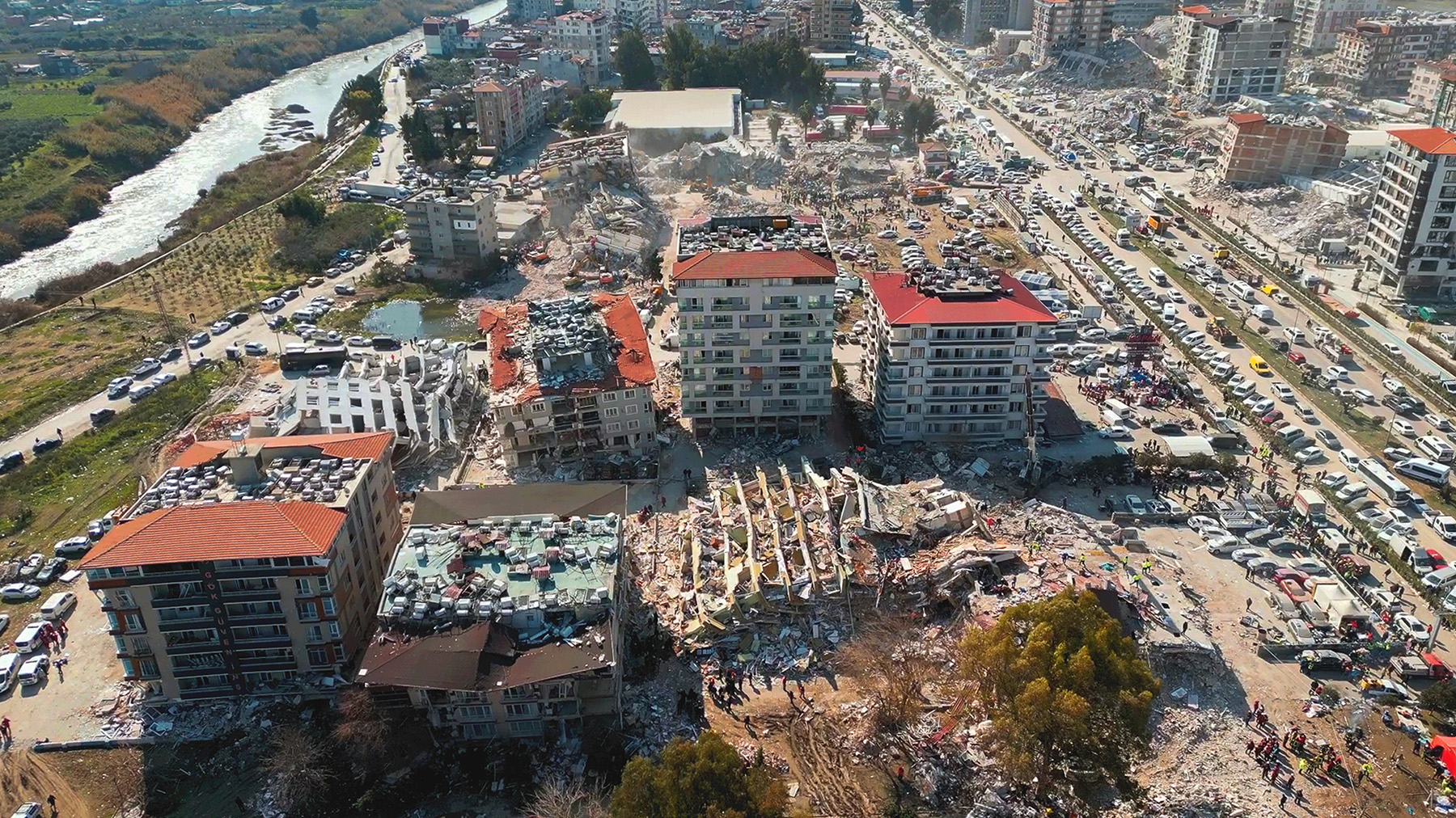
Earthquakes are frightening because they do not damage just one building; they can damage an entire city or multiple cities without warning. It does not seem reasonable to accept collapses of thousands of buildings in a city during 1,000- to 2,500-year MRP ground motion. Worldwide, there are at least 500 cities with populations exceeding 1 million. It does not seem reasonable to accept collapses of thousands of buildings somewhere around the world on average every two to five years.
Not designing structures to the strongest ground motions means that the earthquake risk is not completely mitigated. The unmitigated risk is either self-insured or transferred to an insurance company for a fee (premium). Insurance companies closely monitor their aggregate exposure in densely populated areas. In high-seismic urban areas, earthquake insurance is so expensive that most structures are either under-insured or uninsured. Most owners’ only recourse is to be bailed out by the government after a major disaster.
When science is uncertain, engineering needs to step up to provide assurance. In the middle of an earthquake, the occupants of a building need assurance that the building can withstand the strongest ground motions rather than ground motion with an MRP of 1,000 to 2,500 years. After the earthquake, they need assurance that the damaged building can withstand aftershocks.
Ground motions of engineering interest have been recorded since the 1930s. By rough estimates, 5,000 recording stations with an average timespan of 40 years have provided 200,000 instrument-years of ground motion data. The strongest ground motions selected from this dataset have a negligible chance of exceedance compared with the chance of exceeding the MCER ground motions.
Energy demand versus acceleration
During an earthquake, the ground shakes in all directions, but horizontal shaking of the ground is much more damaging than vertical shaking because structures are designed for gravity load with a high safety margin.
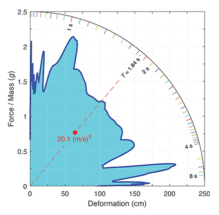
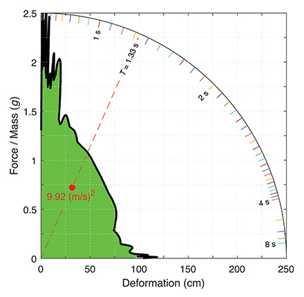
Due to its heavy mass, a structure does not move in unison with the ground. It is deformed by horizontal shaking of the ground. Figure 1 shows the deformation demand on nominally damped structures of various strengths due to the strongest ground motion recorded during the 2023 M7.8 Türkiye-Syria Earthquake. The vertical axis is the lateral strength per unit mass of the structure; it is in units of acceleration due to gravity (g = 9.81 m/s2). The horizontal axis is the deflection of the center of gravity of the structure.
motion recorded during the 2023 magnitude M7.8
Türkiye-Syria Earthquake. (Image courtesy of
Praveen K. Malhotra)
The area enclosed within the demand curve (Figure 1) has units of energy per unit mass (m/s)2; it is the energy demand imposed by the ground motion. The strongest ground motions are the ones with the highest energy demand, not the ones with the highest acceleration. Energy demand is the total energy that can enter the structure from its foundation. The structure repels some of the energy because of its frequency characteristics, dissipates some of the energy through its damping, and absorbs the rest of the energy.
To avoid collapse, the energy absorbed by the structure should be less than its capacity to absorb energy (toughness). It is practical to design structures to withstand the strongest ground motions if these structures possess some key characteristics that will be discussed below.
Toughness versus strength
To prevent collapse, toughness is more important than strength. Strength is the maximum lateral force that can be applied to the center of gravity of the structure before it collapses. Toughness is the maximum energy that can be absorbed by the structure before it collapses. Toughness per unit mass of the structure is called seismic toughness. Like energy demand, seismic toughness is measured in (m/s)2.
building. (Image courtesy of Praveen K. Malhotra)
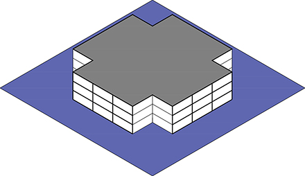
Figure 2 shows the sketch of an extremely tough building with steel special moment frames for lateral load resistance. Figure 3 shows a plot between the deflection of the center of gravity of the building and the lateral force per unit mass. The plot in Figure 3 is known as the capacity curve of the building. The area below the capacity curve is seismic toughness.
moment frame building shown in Figure 2. (Image
courtesy of Praveen K. Malhotra)
High seismic toughness is achieved by using tough structural elements that can yield and absorb significant amounts of energy before breaking. Some examples of tough structural elements are:
- Slender beams with compact cross sections capable of plastic bending rotations of up to 0.08 radians.
- Deep beams with stiffened webs capable of plastic shear rotations of up to 0.16 radians.
- Buckling-restrained braces capable of significant plastic elongation and compression.
ASCE 41, Seismic Evaluation and Retrofit of Existing Buildings, is helpful in determining the toughness of structural elements. The toughness of an efficiently designed structure equals the sum of the toughness of individual structural elements. Horizontal and vertical irregularities such as “torsional eccentricity” and “soft-story” reduce the efficiency of the structure, and hence its toughness.
Ductile elements that contribute to the toughness of the structure must be weaker than such brittle elements as connections. The structure should have high toughness in all horizontal directions because the direction of strongest shaking cannot be predicted.
Also, there should be enough clear space all around the structure so that when it is fully yielded, it can deflect without impacting adjacent structures. Buildings that are built next to each other without any clear space cannot be expected to have high toughness. Strain hardening is a material’s ability to become stronger with continuous yielding. P-Delta is the geometric effect of a deformed structure’s weight on its lateral strength. Strain hardening increases the toughness of a structure, but P-Delta reduces it. The gravity load-resisting system of the structure should not collapse before the lateral load-resisting system reaches its ultimate deflection.
Structures with seismic toughness greater than 5 (m/s)2 are considered extremely tough. Such structures can be collapse proof if they meet some additional requirements outlined below.
Hysteretic versus viscous damping
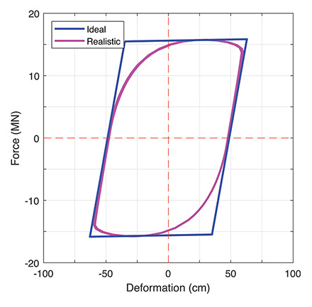
After toughness, damping is the most important factor in collapse-proof seismic design. Damping is a structure’s ability to dissipate vibration energy that manages to enter the structure from its foundation. During elastic deformation, damping of a structure is modeled as viscous. After yielding, hysteresis becomes the primary source of damping, as illustrated in Figure 4.
The area enclosed within the cyclic force-deformation relationship (the hysteresis loop) is the loss of energy per cycle. An ideal hysteresis loop has sharp corners like a parallelogram, whereas a realistic hysteresis loop has rounded corners, as shown in Figure 4.
courtesy of Praveen K. Malhotra)
For a collapse-proof structure, the hysteresis loop should be full rather than pinched. The area of a full hysteresis loop is greater than 70% of the area of an ideal hysteresis loop. The area of a pinched hysteresis loop is less than 30% of the area of an ideal hysteresis loop. For a structure to have a full hysteresis loop, ductile elements of the structure should have full hysteresis loops and they should yield almost simultaneously.
special moment frame building shown in Figure 2.
(Image courtesy of Praveen K. Malhotra)
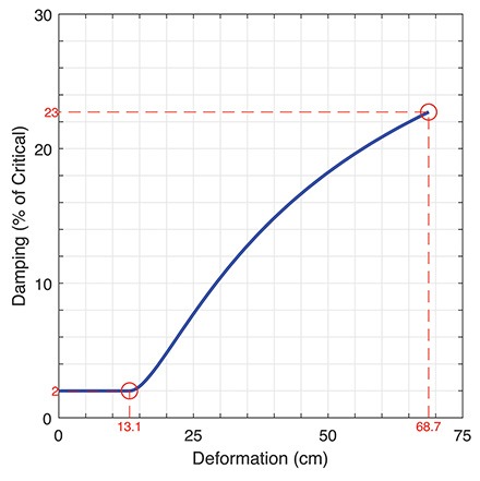
The viscous damping during elastic deformation is much smaller than the hysteretic damping during plastic deformation. Ductility ratio is the total deformation divided by the elastic deformation. Structures with high ductility ratio and full hysteresis loops have high damping. Damping of a yielding structure is not fixed; it changes with deformation. Figure 5 is a plot of damping versus deformation for the steel special moment frame building shown in Figure 2; 23% of critical damping at ultimate deflection is quite impressive.
(Image courtesy of Praveen K. Malhotra)
Figure 6 shows the effect of damping on the demand curve. The energy demand reduces from 20.1 (m/s)2 in Figure 1 to 9.92 (m/s)2 in Figure 6 because of the high damping of the building.
Cyclic versus monotonic
Besides toughness and damping, cyclic capacity is an important factor in collapse-proof seismic design. Gravity and wind loads can be considered monotonic most of the time, but seismic loads are always cyclic. A structure is expected to experience a certain number of cycles during an earthquake and its aftershocks. The toughness and damping of a collapse-proof structure should not degrade significantly from one cycle to the next. Cyclic tests are necessary to confirm toughness and damping characteristics of structural elements.
Mainshock and aftershocks
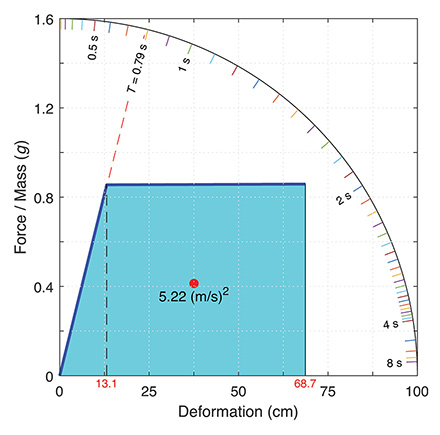
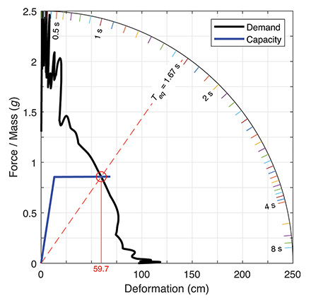
A yielding structure has a limited fatigue life. A collapse-proof structure should not use all its fatigue life during the mainshock because aftershocks are inevitable. Figure 7 shows the demand-capacity equilibrium for the three-story steel special moment frame building subjected to the strongest ground motion recorded during the 2023 M7.8 Türkiye-Syria Earthquake.
story steel special moment frame building subjected to
the strongest ground motion recorded during the 2023
M7.8 Türkiye-Syria Earthquake. (Image courtesy of
Praveen K. Malhotra)
The center of gravity of the building deflects 59.7 cm for 1.5 cycles during the mainshock, but it has the capacity to deflect 68.7 cm for two cycles. The structural damage to the building is (59.7/68.7)2 × (1.5/2) = 0.57 (57%). In other words, the structure uses 57% of its fatigue life during the mainshock. There is enough capacity left to withstand aftershocks.
Conclusion
It is difficult to accept structural collapses that can kill thousands. By relying on toughness rather than strength, it is possible to design structures to withstand the strongest ground motions ever recorded. This may increase the structural cost, but that is usually a small fraction of the total cost of a modern structure.
The design of a collapse-proof structure can be standardized because it does not depend on the site-specific predictions of ground motions. Predictions are highly subjective and uncertain to start with, and they keep changing with time. The cost of insuring collapse-proof structures should be much smaller because such structures will suffer negligible damage during frequent earthquakes.
Praveen K. Malhotra, Ph.D., P.E., M.ASCE, is an expert on seismic ground motions and their effects on structures. He is president of StrongMotions Inc. He is also an inventor, an innovator, and a trainer for seismic topics for ASCE in the U.S. and abroad.
This article first appeared in the September/October 2024 issue of Civil Engineering.
References
AFAD (Ministry of Interior, Disaster and Emergency Management Presidency) (2023). Turkish accelerometric archive v 1.0. Çankaya/ Ankara, Türkiye: AFAD, Earthquake Department.
American Society of Civil Engineers (2017). Seismic evaluation and retrofit of existing buildings (ASCE/SEI 41-17). ASCE.
American Society of Civil Engineers (2022). Minimum design loads and associated criteria for buildings and other structures (ASCE/SEI 7-22). ASCE.
Boore, D. M., & Bommer, J. (2005). Processing of strong-motion accelerograms: Needs, options and consequences. Soil Dynamics and Earthquake Engineering, 25(2), 93–115.
https://doi.org/10.1016/j.soildyn.2004.10.007
Malhotra, P. K. (2005). Return period of design ground motions. Seismological Research Letters, 76(6), 693-699.
https://doi.org/10.1785/gssrl.76.6.693
Malhotra, P. K. (2023). Designing to the strongest ground motions. ASCE.
United States Geological Survey (2023, December 21). Data release for the 2023 U.S. 50-state National Seismic Hazard Model-Overview. USGS. https://doi.org/10.5066/P9GNPCOD
Want to know more about this topic? Join the author for a free webinar on October 10 at noon ET.