By Tom Pullen, P.G., and Michael Haggerty, P.E.
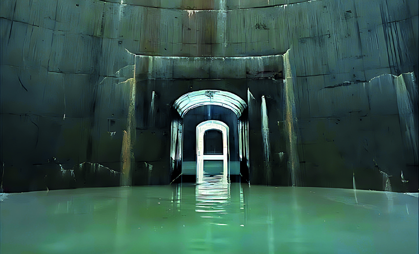
The Minnesota Department of Transportation had a water problem — a flooded roadway problem, to be exact. The solution was an underground stormwater storage facility with a multimillion-gallon capacity.
Interstate 35W, which runs through Minneapolis, is a major interstate in Minnesota that carries upward of 163,000 vehicles per day, according to the Minnesota Department of Transportation, and this number is projected to grow to 250,000 vehicles per day over the next 10 years. Because of expansive land development and loss of permeable surfaces, this stretch of roadway through the city has experienced significant flooding from two-year, 24-hour storm events that cause traffic disruptions and sometimes hourslong lane closures.
Additionally, the existing stormwater tunnel system, which runs beneath the interstate system throughout the Twin Cities of Minneapolis and St. Paul, was prone to surcharging to the point where geysering would blow off the lids of access shafts, closing I-35W for an extended time.
MnDOT needed a viable solution to mitigate roadway flooding and stormwater tunnel surcharging. So in spring 2018, MnDOT collaborated with a team to design and construct an underground stormwater storage facility with a capacity of 14 acre-ft or just over 4.5 million gal. — the first of its kind in Minnesota.
Implementing MnDOT’s unique construction manager/general contractor procurement process was just one part of the collaborative approach that allowed the contractor — a joint venture between Kraemer North America and Nicholson Construction Co. — to be involved in the design phase earlier than is customary. They provided invaluable feedback on cost and constructability during design and construction. Barr Engineering Co. led the design team, which included TKDA and Brierley Associates Corp.
Location and challenges
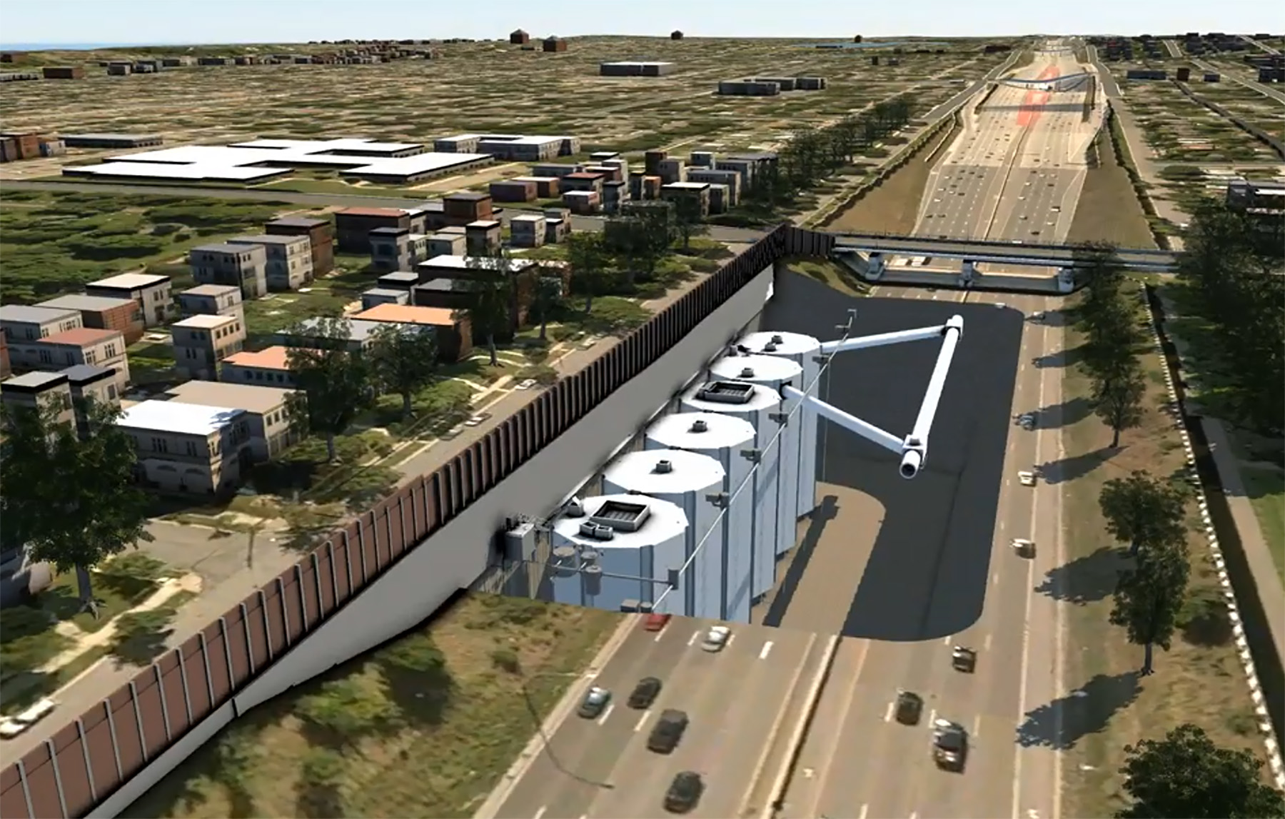
The new underground stormwater storage facility is just south of downtown Minneapolis on the east shoulder of I-35W. The site is bordered roughly by the highway, 42nd Street, 38th Street, and 2nd Avenue. Land use is primarily residential, which posed a separate set of challenges.
The design team used XP-SWMM software to develop flood risk-reduction concepts that took into account complex hydraulic conditions and modeling, high groundwater conditions, and a limited work area. Given the constraints to remain within the existing highway boundary, traditional open-cut and dewatering were deemed impractical. A belowground structure was needed.
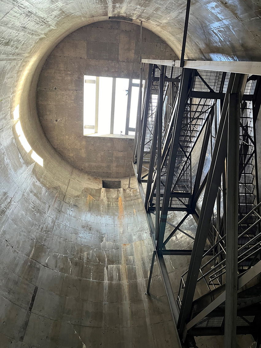
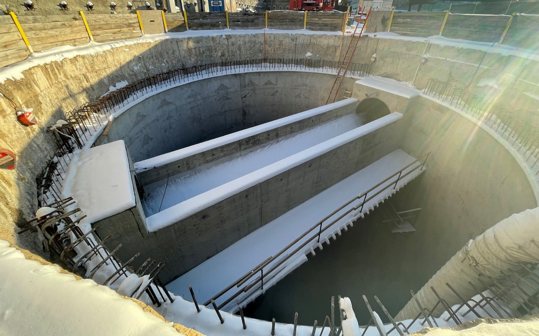
Consequently, the design team evaluated various storage chamber configurations, including a near-surface chamber, a deep cavern, a mid-depth storage option, and a tunnel. Modeling indicated that a structure with about 14 acre-ft capacity would effectively prevent ponding during storms — up to a six-year, 24-hour event. The concept that was progressed to final design consisted of six interconnected 42 ft diameter, 82 ft to 84 ft deep cells that would be constructed employing diaphragm wall technology.
Understanding subsurface characteristics and anticipated ground behavior was paramount to successful project delivery. The design team developed and conducted a geotechnical field investigation to determine the ground variability across the site and to analyze aquifer parameters for the dewatering system design. The investigation included hollow-stem auger and rotosonic drilling; installation of piezometers, inclinometers, and pump test wells; seismic geophysical investigation using multichannel analysis of surface waves; and the design and implementation of field pumping tests.
Information gathered during the geotechnical investigation revealed that the site is near the edge of a glacial erosion channel and comprises variable glacial alluvium outwash. Glacial outwash deposits in the area are typically sand, sometimes with significant zones of gravel or fines.
Sedimentary rock of the Ordovician period (which began some 480 million years ago and lasted approximately 41 million years) underlies the site and is composed of Platteville Limestone, Glenwood Shale, and St. Peter Sandstone, which is nearly pure quartz with fine- to medium-sized rounded grains.
Groundwater beneath the project site exhibited downward and northward gradients. Due to the bedrock valley, the St. Peter Sandstone connects hydraulically to the overlying glacial outwash. The design team’s experience helped in assessing the groundwater regime as well as the hydrological connection between the upper aquifers and underlying St. Peter Sandstone.
Through this analysis it became evident that controlling groundwater pressures would be one of several significant aspects of the design and construction.
Space constraint solution
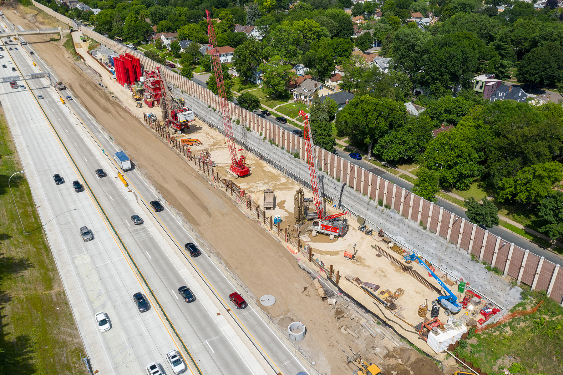
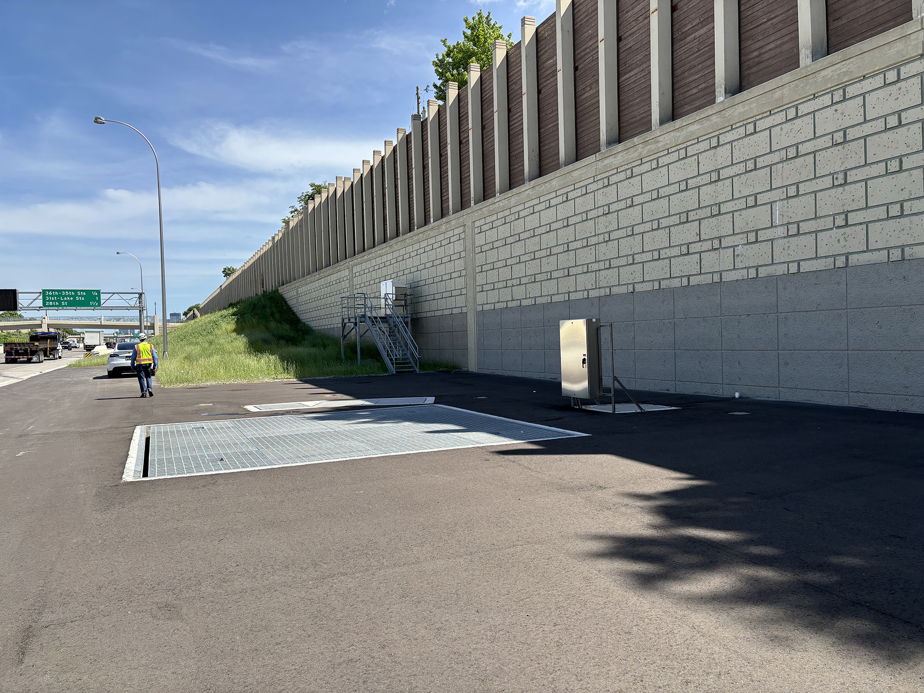
Function and storage capacity were other significant factors related to design and construction. The proposed stormwater storage facility had to fit in the shoulder between the highway and a sound barrier wall parallel to 2nd Avenue, a dense urban residential street.
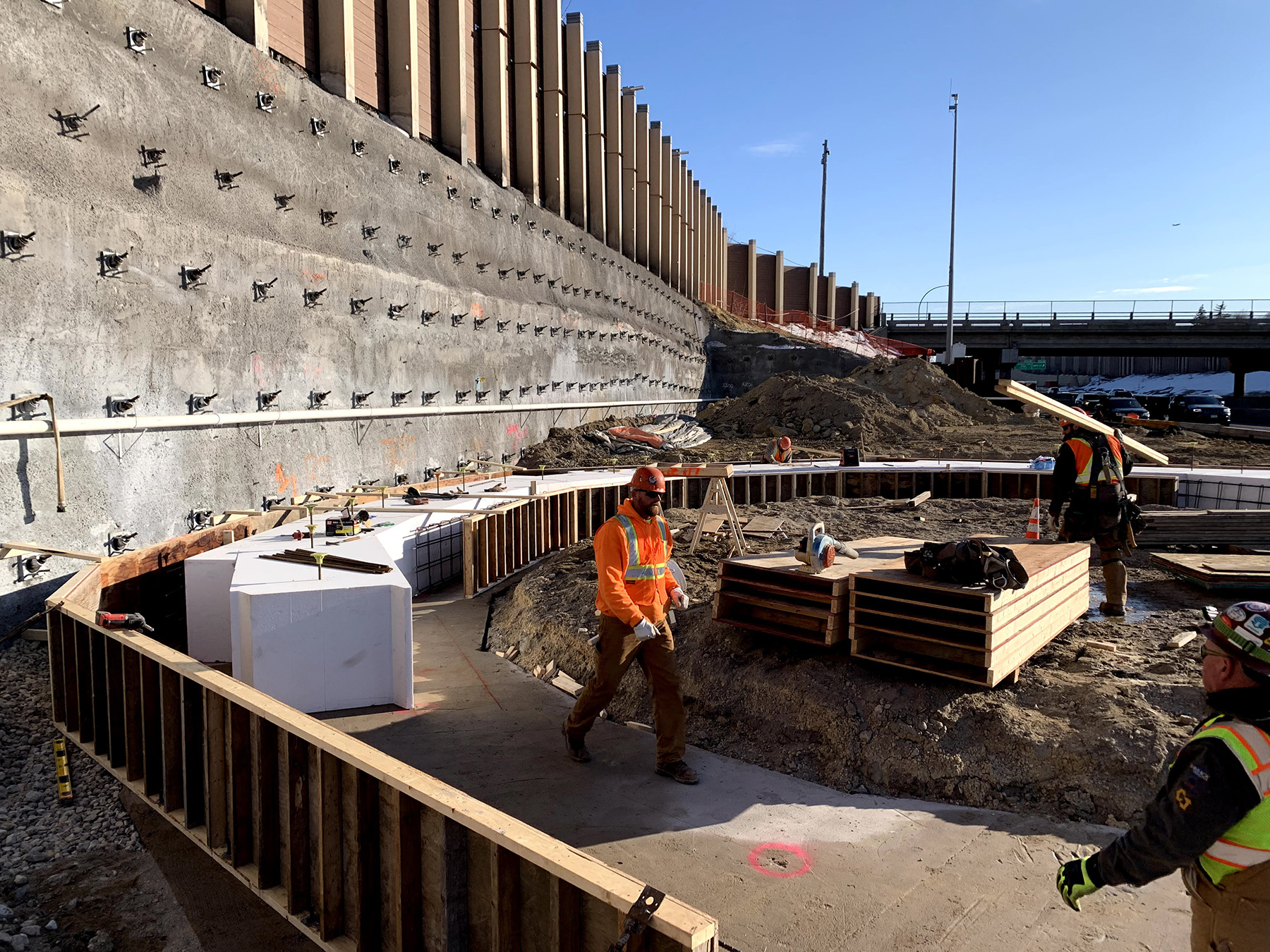
Constructing the underground facility necessitated an innovative approach that combined the removal of an earthen embankment and the simultaneous erection of a massive (630 ft long and 30 ft high) soil nail wall — all of which required travel lane shifts. The team also needed to determine the type of foundation system supporting the existing sound barrier wall, while taking into account MnDOT design and maintenance and protection of traffic standards.
Since creating new space to accommodate the proposed stormwater storage facility was a critical component, the design and construction of the soil nail wall was an early-stage priority. Soil nails ranging from 25 ft to 30 ft in length were strategically placed below the sound barrier wall to avoid conflicts with utilities below 2nd Avenue.
Excavating the embankment progressed from the top down using shotcrete as the initial means of support, followed by installation of soil nail rows in stages as the embankment was removed. Poorly graded sands and silty sands with layers of medium-stiff to stiff clay dominated the retained soil, except for the individual soundwall posts where gravels were encountered. To prevent ground movement at these locations, vertical nails were also installed, which also limited sound barrier wall movement.
Apart from supporting lateral earth pressure and traffic surcharge, the soil nail wall also had to provide base support for the existing sound barrier wall atop the former embankment.
Operational summary
The stormwater storage facility operates by diverting water from an existing 78 in. diameter stormwater pipe in the median of I-35W. The diverted water flows through a two-sided weir structure within cell 1 of the stormwater storage facility. Base stormwater flows do not activate overtopping of the two-sided weir and are routed back to the existing stormwater pipe, which drains north and discharges to the Mississippi River. However, during larger wet-weather events, stormwater that overtops the weir is captured within the stormwater storage facility, filling the cells simultaneously.
The design team constructed a lift station equipped with three pumps to handle dewatering of the facility after a storm event. Two submersible Flygt NP 3171 pumps operate simultaneously to reduce the facility’s water level to about 10% of its capacity, and a solitary non-clog submersible screw pump, Hidrostal E4k-S, takes over to empty the cells.
Water-level sensors positioned within the cells and the downstream 78 in. diameter stormwater pipe monitor the pumps. These sensors ensure that the pumps are activated only when there is sufficient capacity downstream. The lift station and sensors are also linked to MnDOT’s traffic management center for real-time monitoring of operations, and, if needed, preemptive hazard notification to motorists.
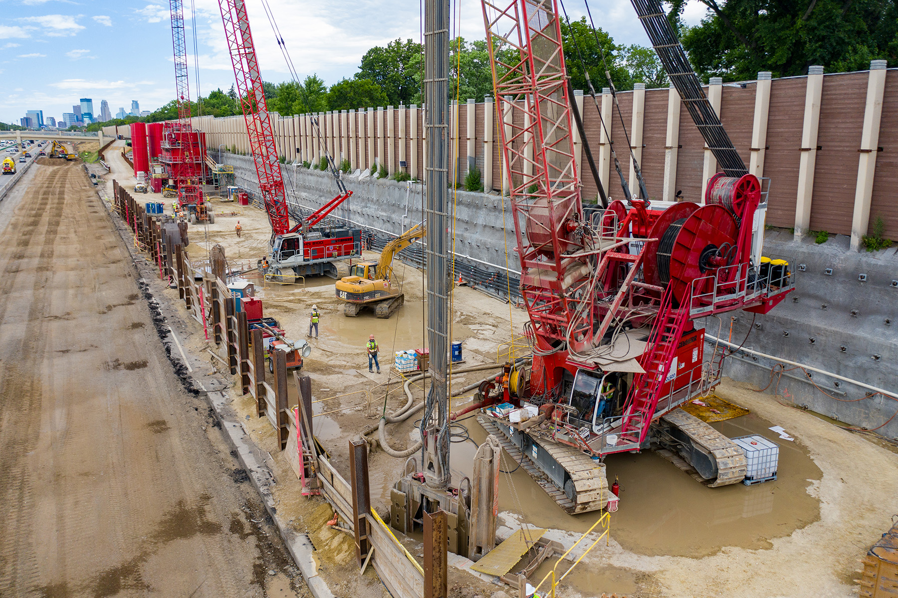
The underground structure was designed to American Concrete Institute code requirements (ACI 350-20) and for a 100-year service life. As mentioned earlier, the design team selected diaphragm wall technology to construct the cells. The 113 ft deep, 4 ft thick diaphragm walls were designed to provide initial support for the construction of the stormwater storage facility cells. Each cell has a circular panel layout, and panels were filled with 5,000 psi concrete. The circular layout resists lateral pressures via ring compression (thrust), eliminating the need for steel reinforcement.
The project team used performance-based criteria for the structural concrete, which included chloride permeability limits. Some other aspects of the structural concrete design encompassed minimizing proportions of Portland cement while using supplementary cementing materials, such as crystalline waterproofing admixture, to reduce permeability and shrinkage as well as to promote self-healing of cracks.
A high-strength, fiber-reinforced concrete topping was placed over each base slab in each cell to provide erosion resistance to the stormwater drop from the weir in cell 1, protect against abrasion from suspended particles, and facilitate post-storm event cleaning activities. The topping also provides positive drainage toward the pump basin at cell 6. The team designed the topping slabs so that they could be replaced without reducing the structural capacity of the base slab.
Hydrostatic loads
Due to significant groundwater pressure, a combination of full hydrostatic and effective lateral earth pressures was the governing load case acting on the base of excavation. Because of the significant depth of excavation, construction equipment surcharge was assumed to dissipate and not contribute to net lateral pressure.
Part of the solution to control the groundwater level was to extend each diaphragm panel to a depth approximately 20 ft below the base slabs of the stormwater storage facility, a move that cuts off flow.
Additionally, work crews installed external depressurization wells that were primarily used to prevent piping failure at the base of excavation and thus reduce internal dewatering. The depressurization wells activated once excavation reached a depth of approximately 45 ft.
Dewatering wells lowered the groundwater level to approximately 14 ft above the final base of excavation, which prevented piping failure once the diaphragm wall shafts were excavated. The depressurization wells remained active until the final lining base slab was installed and doweled to the diaphragm walls, providing a hydrostatic seal.
Design of the 5 ft thick base slabs assumed the transfer of uplift loads to the 4 ft thick diaphragm walls. To transfer load, each cell’s base slab was doweled into the diaphragm walls at regular intervals around the shaft circumference. The design team sized the dowels based on shear friction capacity.
The design assumed the diaphragm walls would support lateral earth pressures in the permanent condition and that leakage could occur over time; therefore, the final wall lining needed to support only the external hydrostatic pressure.
Additional load cases were considered for a full tank with a groundwater level near the ground surface; however, the empty tank condition governed the wall liner design.
The final wall liner resists the applied load via ring thrust, and ACI design code limits governed reinforcement. Bending moment capacity was checked for the moments applied by the roof and base slabs.
The applied moment at the base is a function of the rotational rigidity of the wall liner relative to that of the base slab and diaphragm wall. The applied moment at the top of the shafts is based on rotational stiffness of the wall relative to that of the roof slab.
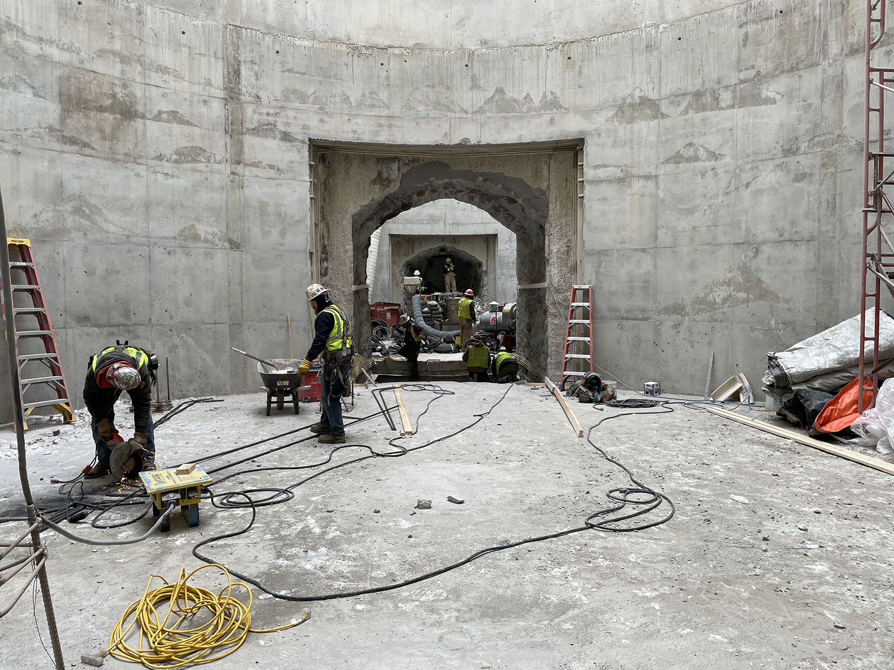
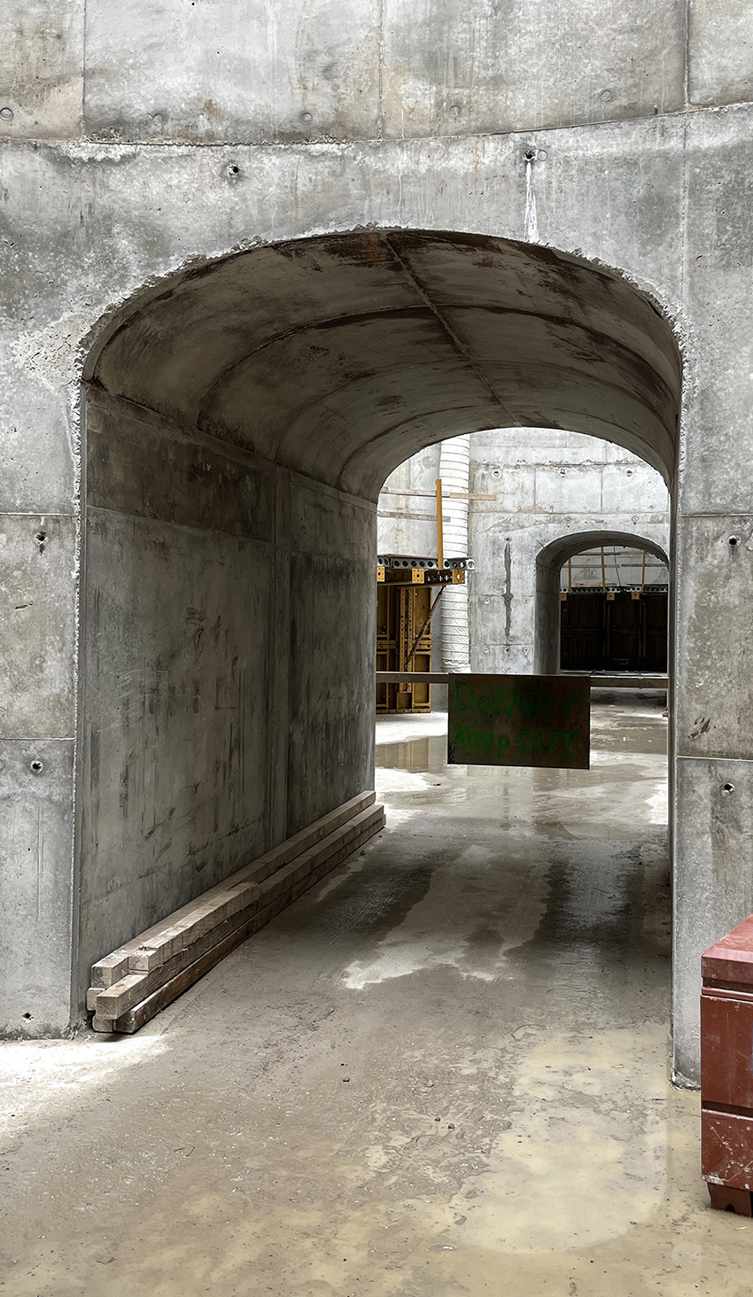
Intercell passages
The six cells are connected by upper and lower passages. The upper passage system serves as an air release pathway during intense rain events and subsequent rapid filling of the individual cells. To provide a means of access for maintenance and periodic cleaning, the lower passages were sized to accommodate skid-steer equipment. The final lining for the passages accounts for full ground and hydrostatic loads. Also, the upper passage design considered vehicular surcharge, given the shallow cover depth.
Passageway excavation
To accommodate excavation of the passageways between the diaphragm wall shafts, the design team installed jet grout blocks with a minimum unconfined compressive strength of 1,000 psi. During the design process, the team developed a 2D finite element model to determine stresses in the ground improvement block.
Based on the principal stress plots, the peak compressive stress occurred at the lower corners of the lower passage, and the peak tensile stress occurred along the base of the opening near the lower corners. For the tension and compression stress checks, the team used a smearing technique to simulate load sharing in anticipation of local crushing or yielding.
Roof slabs
Roof slab design for each cell accounted for vertical earth pressure, traffic surcharge loading, and snow load. For traffic surcharge, a dynamic load analysis was performed with wheel load magnitudes and layout based on the HL-93 design truck from the AASHTO LRFD Bridge Design Specifications. Total design snow load included ground snow load for the Minneapolis area plus snow displaced by snowplows. The cell 2 roof slab incorporated supports for a steel pipe bridge hung from the slab via cast-in anchors.
The roof slabs have openings of various sizes for ventilation and to accommodate personnel and equipment access for cleaning. The larger openings were designed using 3D structural analysis models, and all openings required special reinforcement detailing.
Monitoring
Instrumentation and monitoring were paramount to safety on the worksite. The project was heavily instrumented, with vibrating wire piezometers, inclinometers, and strain gauges. Monitoring was baselined so that the information could be used for the project team to make informed decisions.
Since the deep excavation was approximately 15 ft to 20 ft from active travel lanes during certain periods of construction, the project team installed vertical inclinometers to detect any lateral movement toward the excavation.
The team used strain gauges and prisms to monitor the sound barrier wall and ensure it remained stable during construction. Work crews used automated total stations to survey prisms along the sound wall to measure deflection and movement. Strain gauges were also installed into the cells’ diaphragm walls to monitor strain during excavation.
Remote information sharing of the data was a key aspect of the project, enabling real-time access for all decision-makers.
The CM/GC project delivery process was characterized by continuous feedback and value engineering considerations, including constructability, cost, and real-time scheduling. Through transparent and regular communication, the design underwent several iterations, with MnDOT retaining final decision-making authority.
The team effectively designed and constructed a belowground stormwater storage facility that enhances resilience along a crucial traffic corridor in the Twin Cities.
Tom Pullen, P.G., is a senior project leader for Brierley Associates. Michael Haggerty, P.E., is a vice president and senior geotechnical engineer for Barr Engineering Co.
Project credits
Owner/sponsor
Minnesota Department of Transportation
Contractor joint venture
Kraemer North America, Plain, Wisconsin; Nicholson Construction Co., Canonsburg, Pennsylvania
Prime engineer and geotechnical studies
Barr Engineering Co., Minneapolis
Geotechnical investigations and pump testing
Braun Intertec, Minneapolis; Traut Companies, St. Joseph, Minnesota
Geophysical studies
Olson Engineering Inc., Wheat Ridge, Colorado
Hydraulics and hydraulic structures
Barr Engineering Co., Minneapolis
Civil engineering, lift station design, and electrical
TKDA, St. Paul, Minnesota
Geostructural and underground design
Brierley Associates Corp., Minneapolis
Traffic control
HZ United, Plymouth, Minnesota
Supervisory control and data acquisition (SCADA)
In Control Inc., Fridley, Minnesota
Concrete supplier
Cemstone, Minneapolis
This article first appeared in the September/October 2024 issue of Civil Engineering as “Flood Fixer.”