By Robert L. Reid
Seismic concerns guided the design of a new exhibit for the retired space shuttle Endeavour. But first the orbiter and its various components had to be moved and lifted into place.
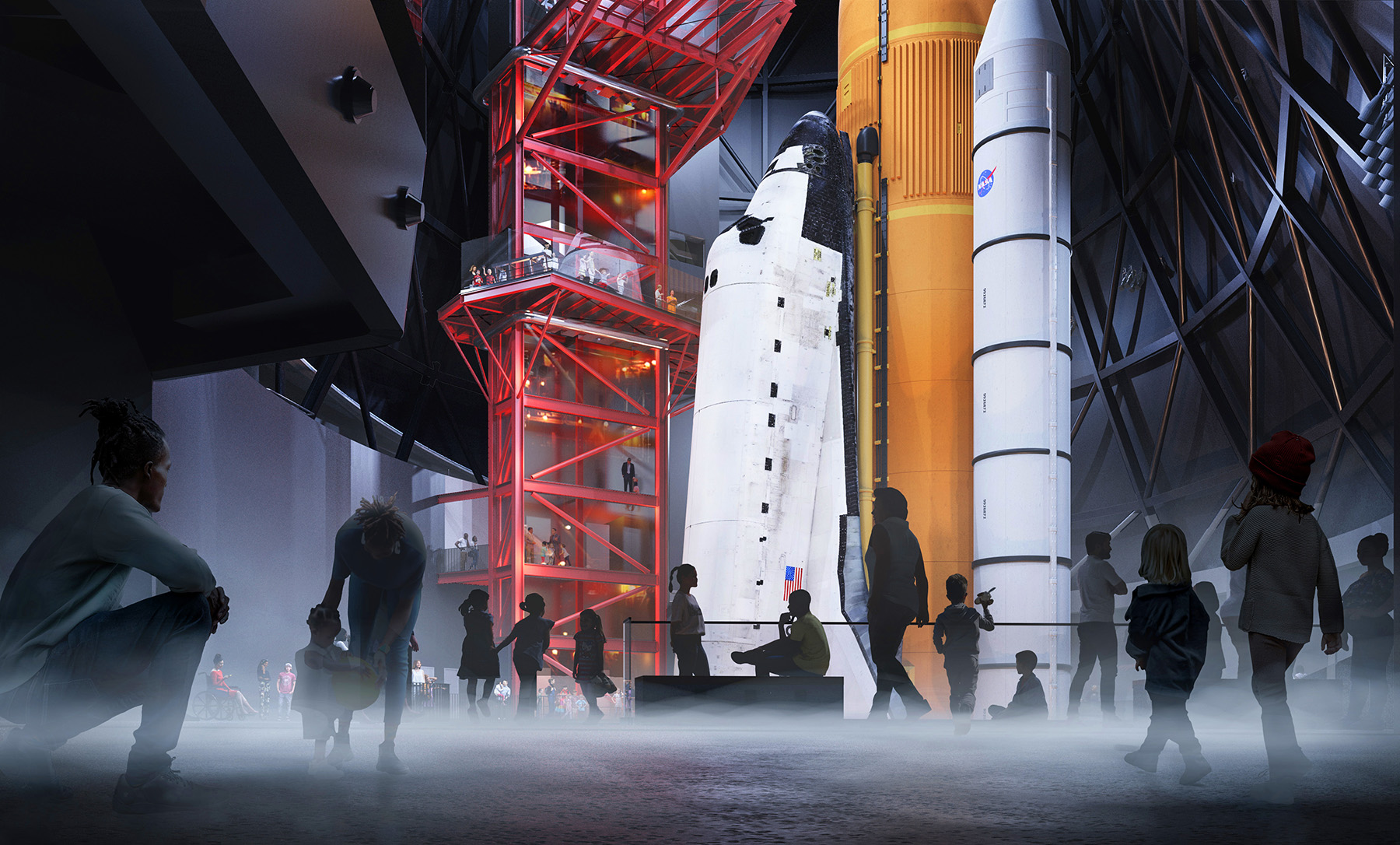
Before being retired in 2012 and incorporated into a science center exhibit, the space shuttle Endeavour orbited the earth on 25 missions — each beginning at the Kennedy Space Center in Florida with a fiery, earthshaking launch that produced nearly 7 million lbs of thrust. Hurtling Endeavour into space in just eight and a half minutes, that tremendous thrust was produced by the three main engines of the shuttle vehicle, also known as the orbiter. Those engines were fed by an enormous external tank and assisted by a pair of solid rocket boosters on either side of the orbiter, which were jettisoned after the first few minutes of flight.
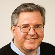
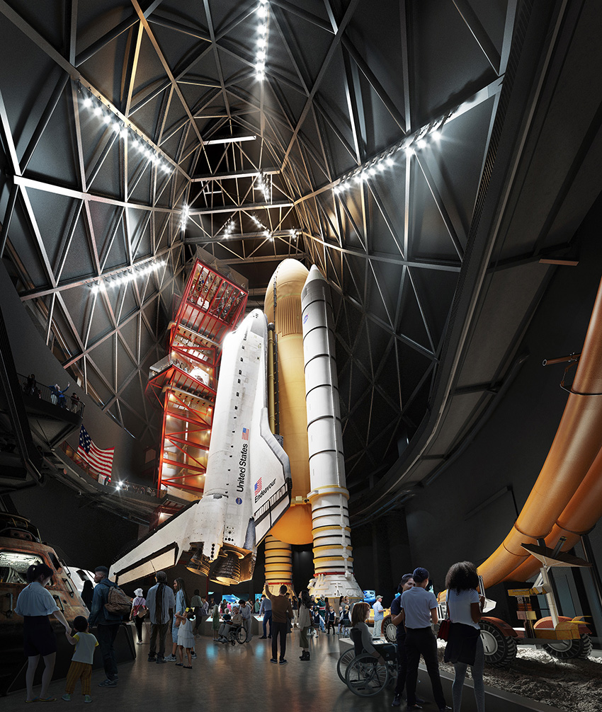
The combination of orbiter, external tank, and solid rocket boosters formed the shuttle’s iconic profile, which is how the retired Endeavour will be displayed for public view in its new home — the California Science Center’s Samuel Oschin Air and Space Center, in Los Angeles. Known as the stacked configuration, because the various components are stacked atop each other, this arrangement will depict Endeavour standing upright as if ready for one more launch.
Although visually dramatic, the configuration created challenges for the engineers who helped design the display. This is because the stacked configuration provides strength in a gravity-defying vertical direction, but it is not very strong in the horizontal direction, according to Atila Zekioglu, S.E., P.E., M.ASCE, a senior principal and design practice area leader at Degenkolb Engineers. Previously, Zekioglu was a principal at Arup and served as the structural engineer of record for the new Oschin building to ensure that it and the Endeavour exhibit within would survive all the demands of future earthshaking events.
The potential of a seismic event was a critical concern during the design of the Endeavour display because the science center is relatively close to several Southern California fault lines. Additionally, nearly everything in the exhibit will be an authentic, historical artifact from the space shuttle program, which makes these components irreplaceable, explains Zekioglu (see “The Real Stuff,” below).
A place after space
Following its final flight into space, Endeavour was moved to the California Science Center in October 2012 (see “A Stellar Move,” Civil Engineering, July/August 2013, pages 72-81). There, the orbiter was housed within a temporary, steel-framed structure known as the Samuel Oschin Space Shuttle Endeavour Display Pavilion, while its permanent home, the 200,000 sq ft Oschin building, was being designed and constructed.
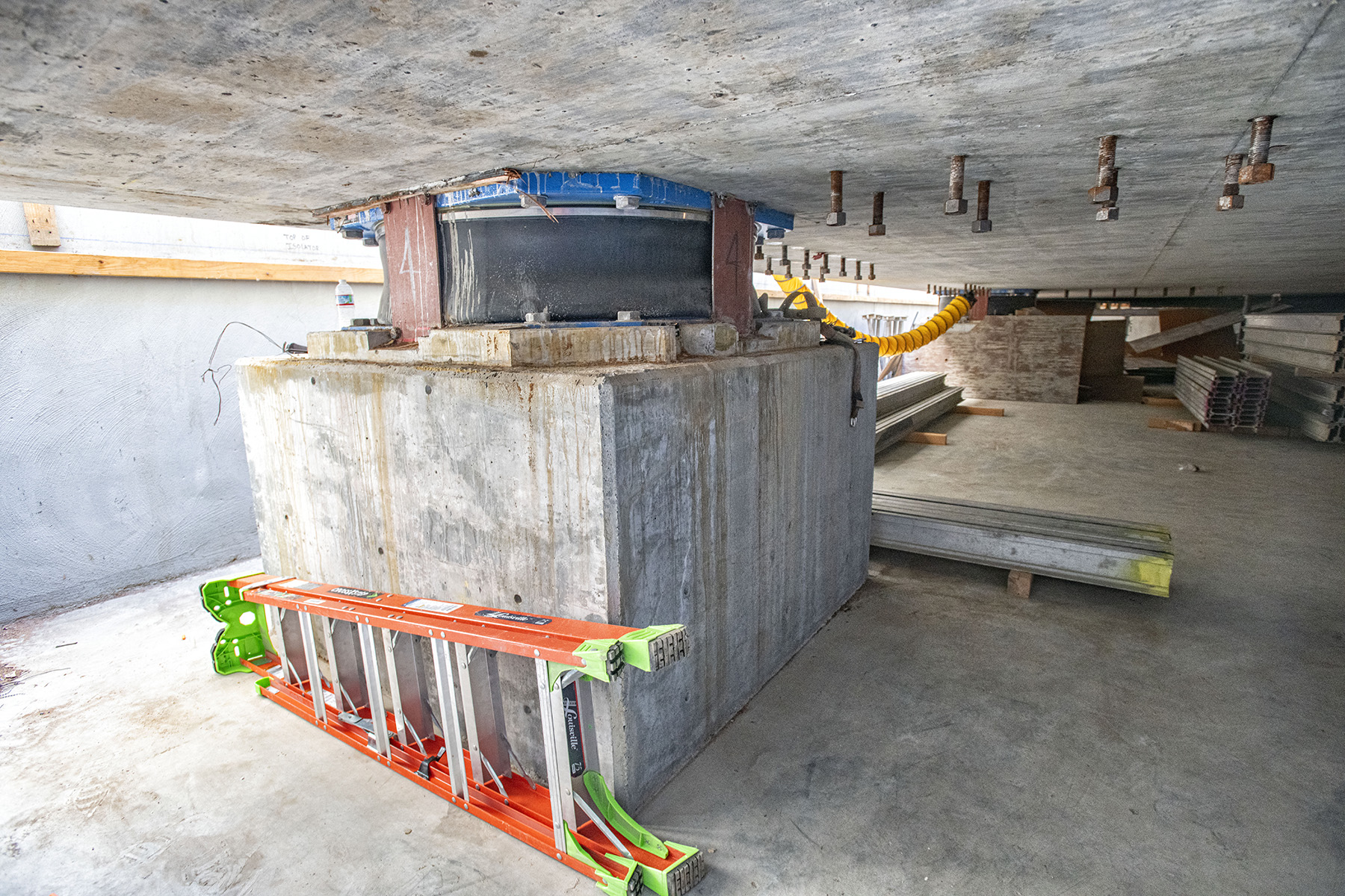
In late July 2023, the science center began a roughly six-month-long process to move the various components of the Endeavour exhibit into position at the planned site of the Oschin building, which was under construction on the eastern side of the science center campus. Dubbed “Go for Stack,” this work first secured the lowest portions of the rocket boosters — the aft skirts — to the exhibit’s foundation: an 8 ft thick concrete pad, measuring 40 ft by 75 ft in plan, supported by seismic isolators above a concrete mat and piles.
The two aft skirts, measuring 18 ft in diameter at their bases and nearly 8 ft tall, are the only parts of the shuttle stack display that will touch the ground. Although the external tank and orbiter will be connected (or mated, in space program terms) to each other and the rocket boosters via bolts, they will essentially be suspended in the air above the concrete pad.
The aft skirts are secured to the concrete pad by four hold-down studs, each 9 ft long and made from a nickel-chromium superalloy known as Inconel. These studs were paired with plates on the top and bottom of the foundation pad and pretensioned, with an allowable margin of error in the alignment of less than 0.10 in., according to Dennis Jenkins, an aerospace engineer and project director for the Samuel Oschin Air and Space Center. Jenkins is an old shuttle hand, having worked for various NASA contractors on all 135 shuttle launches from 1981 to 2011. He leads a team of shuttle program veterans on the Endeavour exhibit and has worked on the permanent displays for the other retired shuttles: Enterprise, Discovery, and Atlantis (see “Still Soaring,” Civil Engineering, April 2014, pages 58-63 and 80).
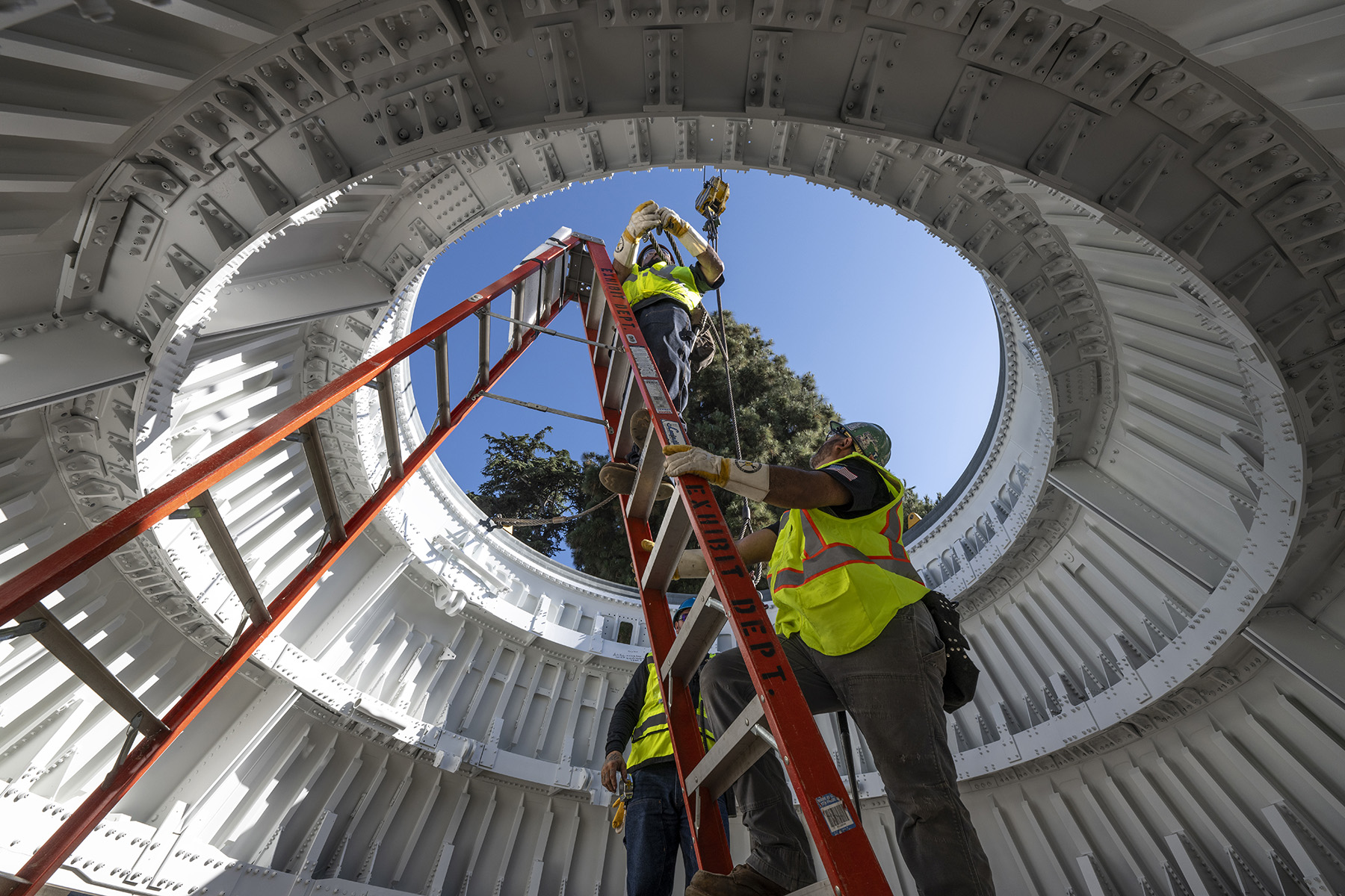
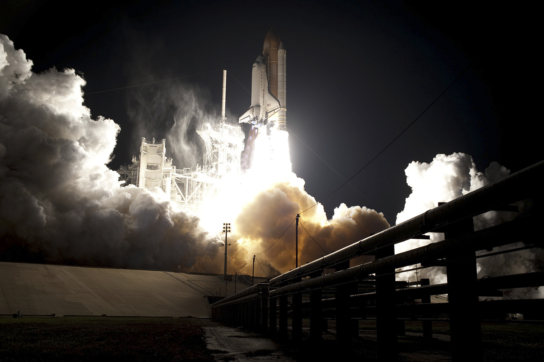
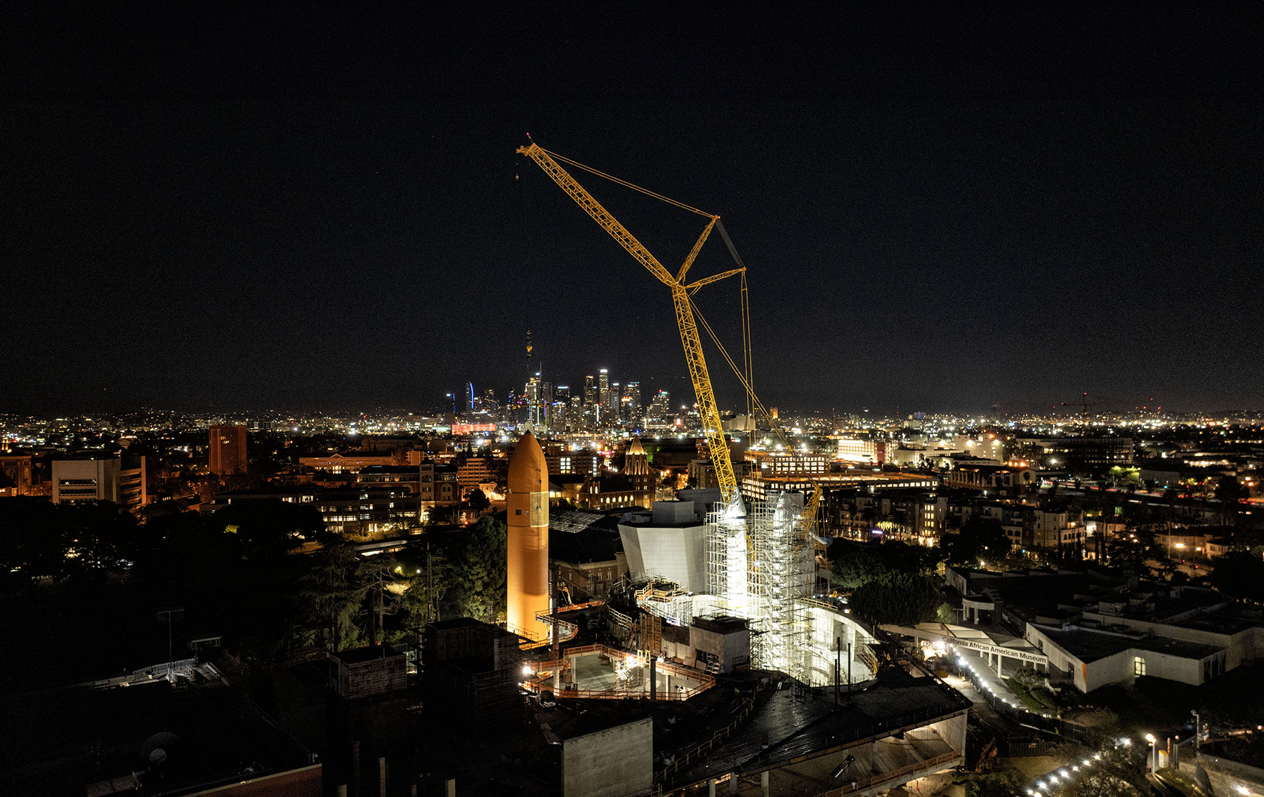
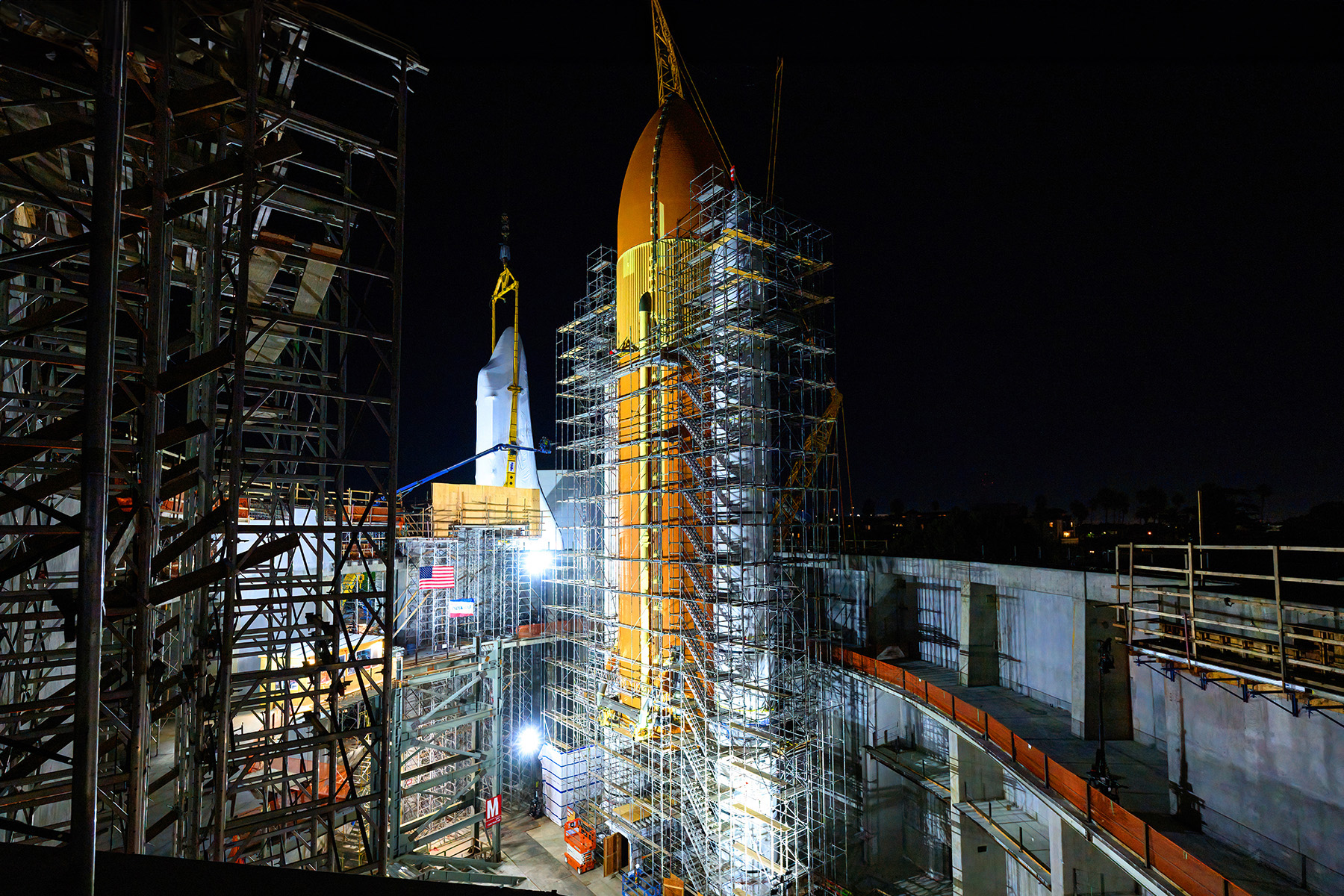
During November and December 2023, the various other sections of the rocket boosters for the Endeavour exhibit — from the rocket motors to the nose cones — were installed on top of the aft skirts, bringing the completed boosters up to their full height of approximately 150 ft. In early January 2024, the enormous external tank — 154 ft long, more than 27 ft in diameter, and clad in an orange-painted insulating foam — was connected to the boosters.
And finally, late in the same month, the 122 ft long Endeavour was moved from the temporary pavilion on the western side of the science center’s facilities to its new and ultimate setting, where it was lifted into place via cranes and connected to the external tank. Initially covered in a protective shrink wrap, the orbiter will remain in place while construction of the Oschin building is completed around it. The shrink wrap has since been removed to eliminate the possibility of mold growth, says Jenkins.
Surrounding structures
The tall, curvilinear, and conical shuttle gallery portion of the Oschin building will be clad in a stainless steel facade and supported by a perimeter-only structure, including 70 ft tall concrete shear walls at the base and a 130 ft tall steel-framed diagrid roof to enclose the large open space. The steel diagrid roof will soar above the shuttle gallery and the roughly 15-story-tall shuttle stack within, says Amie Nulman, S.E., an Arup principal and the firm’s lead structural engineer and project director on the design of the Oschin building.
The shape of the shuttle hall roof, which covers a large void nearly 200 ft tall and 200 ft by 100 ft in plan, was determined by finding a balance between two criteria: first, minimizing the amount of materials required to enclose such a large artifact and the mechanical systems required to condition such a large area; and second, providing room for unobstructed views of the shuttle stack from various locations, says Nulman.
The steel diagrid roof is a triangulated framing system composed of three main element types: verticals, horizontals, and diagonals. The verticals and horizontals were formed using rolled-steel wide flange sections, or I shapes, which are W14 and W18 in this case, and the diagonals are hollow steel sections ranging from 10 in. to 14 in. in diameter.
The project team designed the members to resist any and all applied loads, from vertical gravity loads to horizontal earthquake and wind loads. The members are also connected with built-up welded steel plates at the nodes where the verticals, horizontals, and diagonals intersect. Each of the 140 nodes has a unique geometry that results from the loads being transferred, the shapes of the elements connecting into the nodes, and the shape of the shuttle roof at that location.
The triangulated diagrid structure is an efficient and resilient framing system resulting in the use of lighter and smaller members, using less material and having less embodied carbon in the structure. Also, to reduce the risk that the building around the shuttle stack might collapse on top of the artifacts during an earthquake, “we used a performance-based design, or alternate means of compliance to the building code, to design the tall, diagrid steel-braced frame roof to a higher level of seismic performance than a typical building-code-based design,” Nulman says.
A steel-framed tower, similar in appearance to the gantries used at the Kennedy Space Center, will be erected adjacent to the shuttle stack to provide visitors with multiple viewing platforms to examine up close the orbiter and its accompanying external tank and rockets. The gantry tower is a building-code-based, steel-braced frame design and did not require seismic isolation. The gantry sits on a piled foundation at the base and is integrated with the surrounding shuttle gallery and building structure, Nulman explains.
The Oschin building will feature three levels and a basement. The primary gravity framing is concrete flat slabs supported by concrete columns and concrete shear walls. The foundations will consist of 24 in. diameter, 55 ft deep full-displacement, cast-in-place concrete piles, and the roof will feature a metal deck with steel beams supported on concrete columns and walls.
Visitors will also be able to move easily between the Oschin building and the science center’s existing adjacent buildings, although the two structures will be separated by a seismic joint.
As of press time, an opening date for the Oschin building, including the shuttle stack exhibit, has not been announced.
Shifting challenges
Arup’s engineers have been involved with the seismic aspects of the Endeavour exhibit since 2011, when they started speaking with science center staff and engineers from Boeing who had worked on the space shuttle program. These conversations helped to determine key details — such as the weight and stiffness of various components, as well as damping data — for a comprehensive structural seismic analysis model, Zekioglu says.
From that initial model, he then designed a seismic isolation system that featured four multistage, friction-pendulum isolators that protected the orbiter for a dozen years as it was on display in an elevated, horizontal configuration in the temporary pavilion. That display did not include the external tank or rocket boosters.
During the early stages of the design for the shuttle stack project, “we were going to use replica elements and built-up structural steel frames with cladding” to support Endeavour in its vertical configuration, says Nulman. But as the science center collected the original artifacts, as well as authentic attachment hardware, “this shifted our challenge from replica framing to determining how to support a 180 ft tall, 500,000 lbs multi-element artifact in a seismically active region,” Nulman says.
The former shuttle program engineers from Boeing helped Arup’s team “understand early on that the forces Endeavour could experience during an earthquake in (Los Angeles) actually exceeded the loads that it was designed to resist as it was launched from the ground and throttled up and out of the earth’s atmosphere,” Nulman explains. “So, our first move was to reduce the demand on the stack from earthquake loads by using base isolators below the concrete pad at the base of the stack.”
Seismic scenarios
Using a mathematical representation of the shuttle stack that Boeing had created during the space program, Arup’s team ran an analysis of multiple earthquake scenarios using the LS-Dyna atypical structural analysis software system. Although this software is commonly used to simulate and evaluate damage from car crashes, Arup selected it for the Endeavour project because it enabled “us to combine the mathematical representation of the shuttle stack that we got from Boeing with the structural support elements that we were designing,” Nulman says.
Moreover, the system was “superior to typical structural software in performing the analysis needed to capture the stack’s behavior on the base-isolated pad during multiple earthquake scenarios,” according to Nulman.
Arup’s team simulated 11 potential seismic events, using X, Y, and Z acceleration versus time data. These simulations considered millions of data points involving “little slices of movements, velocities, and accelerations in every second of a quake,” Zekioglu says, “so we (got) all these good seismic response parameters ... to make sure our seismic isolators were sized correctly.”
The analysis also considered the forces at the connection points, such as those between the orbiter and the external tank, as well as horizontal and vertical earthquake movements to ensure the shuttle stack’s overall stability. The seismic simulations ultimately indicated the need for an isolator displacement capacity of 30 in. in all horizontal directions.
The simulations even considered what might happen if the earthquake predictions were underestimated — a concern, given the increasingly powerful quakes that have occurred around the world in recent decades, Zekioglu notes. “So, we actually tested the isolators for displacements exceeding 30 in., and what that would mean ... if the metal ruptures and the (isolator elements) move another 4 to 5 in.”
Fortunately, the data showed that “the stability of the system will be completely maintained” even in the event of greater displacements, Zekioglu says.
Performance planning
Based on these simulations, the project team adopted seismic performance goals for a design-basis earthquake with a 475-year return period and a maximum considered earthquake with a 2,475-year return period, Zekioglu says. The DBE could be generated by a seismic event of 6.5 to 7.5 magnitude, which encompasses 90% of all potential earthquakes in the region over the next 50 years, while the MCE could be generated by a seismic event of 7.5 to 8.5 magnitude, which encompasses 98% of all potential earthquakes within the next 50 years, Zekioglu says.
Under a two-tiered approach, the project team designed the shuttle stack seismic protection so that the historical artifacts would not sustain damage during a DBE or MCE. Likewise, although the diagrid roof and viewing tower gantry are not base isolated, they were designed with structural members and connections robust enough that they should not need any repairs following a DBE. To avoid excessive costs, however, those structures above and around the shuttle stack might need some retrofits following the more powerful MCE, Zekioglu says.
The seismic solutions developed to achieve those goals featured six triple-friction, pendulum-type isolators, each roughly 5 ft in diameter, installed beneath the concrete slab at the base of the shuttle stack. The isolators rely on “a series of concave, spherical, highly polished steel plates with a puck at the center that effectively glides around between the plate surfaces during an earthquake, dissipating or absorbing energy from the earthquake ground motions and allowing the stack to glide around gently, avoiding much of the whiplash effects and forces that structures experience during earthquakes when they are locked to the ground,” explains Nulman.
Making the final move
Endeavour’s final journey involved a move of about 1,100 ft, which is the distance between the temporary pavilion and the site of the new Oschin building, says Jenkins. The move began by first raising the orbiter on a series of self-propelled motorized transporters. The spacecraft was then backed out of the temporary pavilion, which had to be partially disassembled so that Endeavour’s 78 ft wide wingspan could clear a nearby building on a property adjacent to the science center’s site.
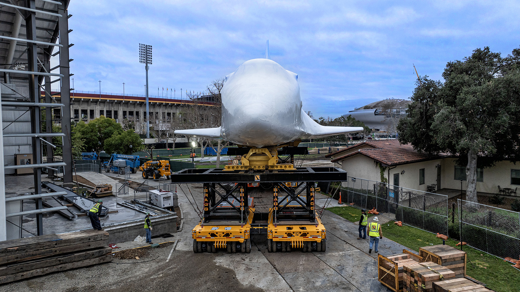
Because the route between the temporary pavilion and the Oschin building ran along State Drive at a slightly lower elevation than the pavilion, ramps and several hundred cubic yards of fill helped to level the land over which the transporters had to carry the orbiter. Rain complicated the move, Jenkins adds, because the leveling efforts had covered the only two storm drains on State Drive, creating a temporary mess.
When Endeavour reached the Oschin building site, it was attached to an enormous sling to be lifted into place on the stack. There were only seven very specific locations on the orbiter where pieces could be attached: two on each side of the spacecraft where the sling attaches and three along the bottom of the fuselage where the external tank attaches, Jenkins notes. Because attaching the sling to Endeavour was a potentially tricky maneuver, the team allocated eight hours to the effort, but the work went so smoothly they completed the task in less than two hours, Jenkins says.
Although the sling was the same device that the Kennedy Space Center had used to lift its shuttles, there was a critical difference. In Florida, the shuttle lifts were performed inside the Vehicle Assembly Building using bridge cranes positioned directly above the orbiters. But at the science center, a trio of boom cranes outdoors was used, which created greater challenges because of the potential for the cranes to swing, the constantly changing angles at which they operated, unpredictable deflections, and even the different wind conditions at the top of a crane 350 ft in the air versus the winds closer to the ground.
Once lifted, Endeavour was “soft mated” to the rest of the stack components — meaning everything was lined up roughly and loosely bolted in place. The exact alignment was not fixed, and the bolts were not torqued, until the “hard mating” on the following day, January 30, Jenkins says.
Although the Endeavour shuttle stack will be the centerpiece of the Samuel Oschin Air and Space Center, the facility will also feature more than 100 hands-on and interactive exhibits, as well as other authentic artifacts from aerospace history, including capsules that flew in space during the Mercury, Gemini, and Apollo-Soyuz programs.
The Endeavour project has been a highly personal effort for some of the key engineers. For Nulman, designing the structure of the Oschin building and the support system for Endeavour was especially rewarding because one of her grandfathers, Bill McAnally, had been a mechanical engineer on the space shuttle program who contributed to the design of several key moving parts on the orbiters, including the cargo bay doors, landing gear, and thrusters. “I feel that my work, structurally engineering the building that protects the space shuttle Endeavour ... is an homage to my grandfather’s life’s work as well as the positive influence that he had on me,” Nulman says.
For Zekioglu, working on the Oschin building and the Endeavour exhibit has been “one of the most fascinating journeys” of his life. As a boy growing up in Cyprus, he would watch the Apollo space launches on television. Later, at the start of his engineering career in Los Angeles, he was involved in the seismic strengthening of NASA’s Neil A. Armstrong Flight Research Center at Edwards Air Force Base, where he could watch the shuttles land.
“But I never imagined I would have the pleasure of being so connected to Endeavour, especially, and spending time with the people who devoted their lives to the space shuttle program,” Zekioglu says, adding that the effort “reminds me of what I really value from my engineering education.” He points to the excitement of learning new things, sharing knowledge with colleagues, and focusing on a “bigger mission,” which in terms of Endeavour means “preserving this national treasure for decades to come.”
SIDEBAR
The real stuff
Although the Endeavour exhibit project initially seemed destined to pair the authentic orbiter with replicas of the other space shuttle components, reality intervened — in the sense that real versions of most of the equipment were eventually found and acquired.
The solid rocket boosters, for example, were donated by Northrop Grumman (which had acquired Orbital ATK, the original manufacturer of the boosters), says Dennis Jenkins, the project director for the Samuel Oschin Air and Space Center and an aerospace engineer who has been involved with every space shuttle launch. Like the orbiter itself, the boosters were a reusable part of the shuttle stack. When jettisoned shortly after launch, the two boosters would drop into the ocean via parachute and be recovered. Composed of different components, the boosters would be disassembled and reassembled between shuttle missions.
Finding a version of the shuttle’s external tank that had flown in space was impossible, however, because the tank was the one component of the shuttle stack that was not reusable; it detached from the spacecraft and burned up in the earth’s atmosphere just before the shuttle reached orbit. Thus, a new tank was required for each shuttle launch.
For the Endeavour project, the science center acquired an external tank — designated ET-94 — that had been constructed for the space shuttle Columbia but never used. Following the destruction of Columbia as it returned from orbit in 2003, the ET-94 tank was used as part of the accident investigation. In that role, large chunks of the insulating foam that surrounded the tank — which on a shuttle mission would have held supercold liquid hydrogen and liquid oxygen — were removed and examined. Later, the tank suffered other damage, mostly aesthetic, while being stored at NASA’s Michoud Assembly Facility in Louisiana. The science center spent six years restoring ET-94, Jenkins says.
There was one piece of the shuttle’s original hardware that the science center did not try to install in the new Endeavour exhibit: the hold-down studs that secured the rocket boosters just prior to launch. For one thing, the exhibit studs had to be much longer than those NASA had used at the Kennedy Space Center. But also, NASA had used a frangible nut on top of each stud that was explosively fractured to separate the boosters from the launch pad — not an ideal feature in a crowded public setting.
Robert L. Reid is senior editor and features manager of Civil Engineering magazine.
Project credits
Owner
California Science Center, Los Angeles
Architect
ZGF, Portland, Oregon
Building engineers
Arup, Los Angeles office
General contractor
MATT Construction, Santa Fe Springs, California
Shuttle stack moving and lifting consultant
Bragg Cos., Long Beach, California
Exhibit design
Evidence Design, Brooklyn, New York
Seismic isolators
Earthquake Production Systems, Vallejo, California
This article first appeared in the January/February 2025 issue of Civil Engineering as “Endeavour Upright.”