Claim Reduction is a monthly series by the ASCE Committee on Claims Reduction and Management designed to help engineers learn from problems that others have encountered. In this article, ASCE Distinguished Member James R. Harris describes issues associated with incorporating engineered products in a design. Several claims have been made against engineers regarding the performance of engineered products, and reliance on manufacturer data may not be sufficient to avoid liability.
By James R. Harris, Ph.D., P.E., NAE, F.SEI, Dist.M.ASCE
Imagine a tall residential building with projecting balconies on every floor – it looks like a radiator with fins, and thermodynamically it behaves as such. One way to change that behavior is to install thermal breaks between the balconies and the interior floor slabs. The drive for energy conservation and sustainability is something that structural engineers will not be able to stop, nor should they. However, structural engineers need to recognize and avoid problems, which won’t necessarily be easy.
Thermal break connector systems for concrete slabs have been popular in Europe for several years, and they are becoming more popular in the U.S. Common connectors include a plastic box filled with thermal insulation and crossed by a few reinforcing bars and compression bearing blocks. Figure 1 shows a plan view of a common balcony, and Figure 2 shows a few generic thermal break connectors for concrete slabs (there are many more variations, including connectors capable of transmitting shear and moment in two directions). The reinforcing bars across the joint are sometimes stainless steel, which transmits less heat than carbon steel, and the bearing blocks may consist of proprietary materials.

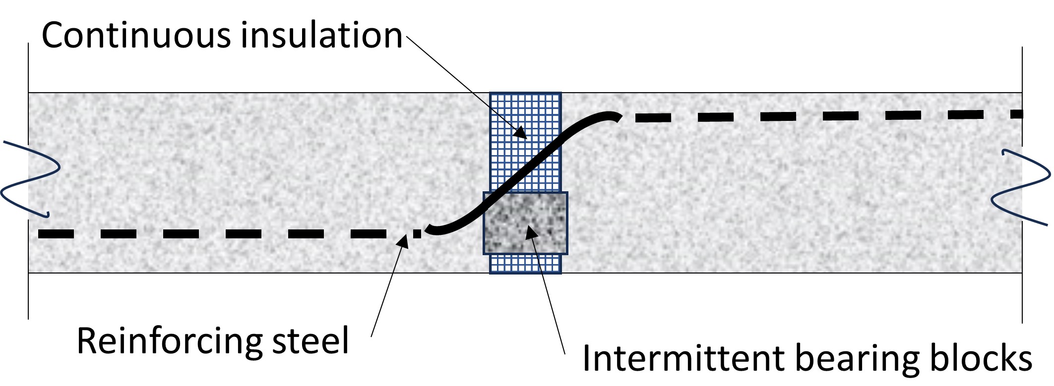
a) Shear-only connection
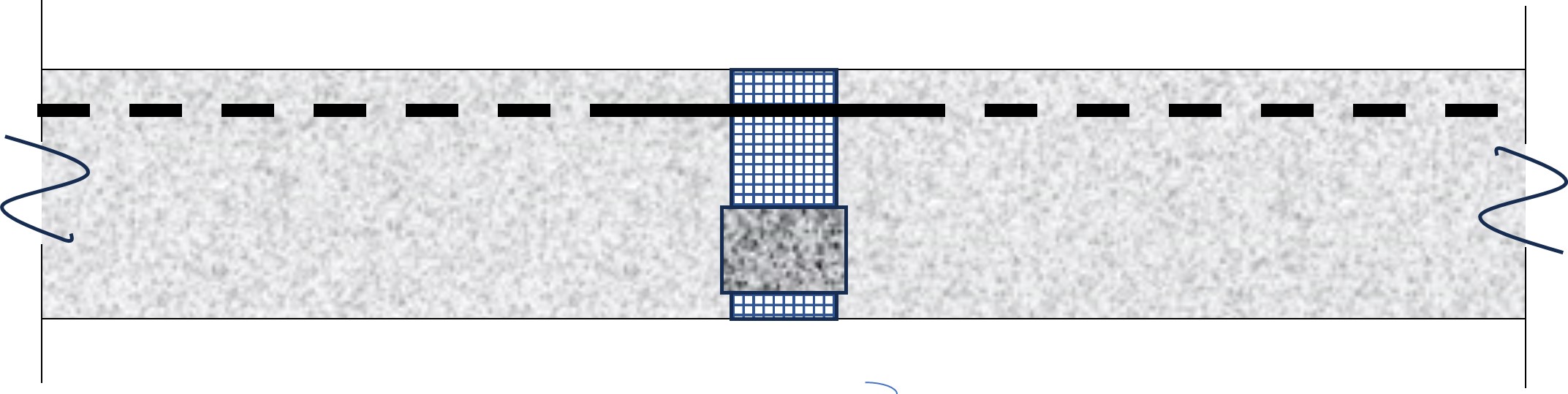
b) Moment and shear connection
The one-way shear-only connection is more prevalent than one might expect. Exterior slabs are subject to different thermal and shrinkage demands than interior slabs, and balcony configurations that would generate restraint to those differences create a demand for relatively soft joints insofar as in-plane membrane forces (concrete shrinkage and thermal movements) are concerned. The one-way shear-only connection provides that.
The insulation in the plastic box provides thermal separation. Nearly all types of insulation, whether foam or fibrous, are mostly air. A great many applications require that the TBCS provide a fire separation, and there are multiple ways of achieving that. It is wise to insist on certification from a reputable entity regarding the fire-resistant properties of the TBCS.
Much of the early experience with TBCS in Europe has been in buildings where the exterior wall is a structural bearing wall. Thus, the balcony was supported on a vertical element with very high stiffness regarding vertical movement. Such systems are not common in the U.S., where most concrete residential buildings employ a two-way flat plate structural system. The flexibility of the main slab makes computing the forces transmitted by the TBCS from the balcony to the main slab complex. It is not feasible to obtain reliable answers by considering only the flexibility of the connectors while treating the main slab, the balcony slab, or both as rigid bodies. Doing so inevitably means the computed forces will not represent reality.
Figure 3 shows exaggerated deformed shapes of shear and moment connectors. The stiffness properties, represented by the ratios V/Δ and M/θ, are necessary for a rational analysis.
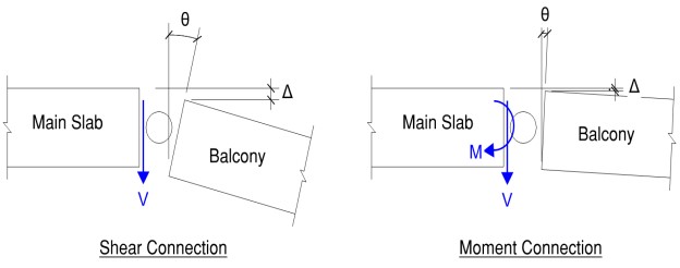
Figure 3: Forces transmitted through TBCS to the main slab and resulting deformations in the TBCS
This leaves the structural engineer of record in a dilemma. If the design of the TBCS is delegated to the contractor and thus to its subcontractors and suppliers, it is impossible to complete the design of either the main slab or the balcony slab. TBCS by different manufacturers come with different stiffness properties, so selecting one as the basis of design may reduce competition among suppliers.
Furthermore, the stiffness and strength values provided by suppliers must be viewed with appropriate skepticism. Clearly, the stiffness properties will depend on the size, spacing, and material of the bars and bearing blocks crossing the joint, the vertical distance between the bars and the bearing blocks and their geometric configuration, and the stiffness of the concrete in both slabs. Some manufacturers provide data that does not seem to consider all these parameters. There is no substitute for providing values for stiffness and strength based on accredited and vetted physical tests. It is best if the tests provide behavior over a full range of deformations so the SER can assess if the TBCS is ductile or brittle. There should be tests over a range of realistic thermal cycles; the durability of TBCS compared to reinforced concrete is not well understood. Some existing products have certifications based on acceptance criteria that do not explicitly consider all these variables.
One example of what can go wrong: A structural engineer designed a two-way post-tensioned flat plate structure with mild reinforced balconies and computed deflections ignoring any flexibility in the TBCS. The TBCS engineer computed deflections of a balcony accounting for the flexibility of the TBCS but ignoring all deflections (and rotations) of the PT main slab (and also ignoring cracking, creep, and shrinkage in the balcony slab). They both arrived at the same value for deflection at the tip of the balcony, thus increasing confidence in their independent solutions. Unfortunately, the actual deflection of the balcony tip was several times the computed value.
A more common problem: the TBCS engineer assumes the main slab does not deflect in response to the loads imposed by the connectors, with the result that the computed reactions are erroneous. The flat plate so common in the U.S. is not rigid. The significance can be minor, especially if the TBCS has significant ductility, or it can be serious if it becomes a safety issue.
The bottom line for SERs: do not expect a balcony slab supported on a joint in which the concrete is mostly replaced by air to behave as a monolithic slab, and do not believe manufacturers representations and calculations without some reality checks. If you delegate the design of the connectors, you need to have confidence in the basis for the delegated engineer’s work (assumptions, physical tests, calculations, etc.), then you need to see if the reactions coming back from that engineer are what you expect and that your structure can support those reactions. You may have to provide information to the manufacturer’s engineer that permits that engineer’s design analysis to account for the flexibility of the structural slab.
And finally, a plea to the TBCS industry: for your product to succeed in the U.S., recognize the realities of residential concrete structural systems and incorporate the sophistication in your products and design analysis necessary to provide safe and serviceable installations. Without this, the probability of problem projects is so high that people will reject the use of TBCS, and the objective of this step towards sustainable design may be lost.
James R. (Jim) Harris is an active member of several committees that produce national standards for structural engineering practice and is a former chair of the committee that produces ASCE/SEI 7 Minimum Design Loads for Buildings and Other Structures, and its subcommittee for seismic design. He has also served on ACI Committee 318, which prepares Building Code Requirements for Structural Concrete, and on the AISC Committees that prepare the Specification for Structural Steel Buildings and the Seismic Provisions for Structural Steel Buildings. He was elected to the National Academy of Engineering for contributions to the development, improvement, and implementation of modern standards for the design of buildings.
Harris received his undergraduate education in civil engineering at the University of Colorado at Boulder in 1968. After consulting in Denver for five years, he earned his master’s and a doctorate in civil engineering from the University of Illinois, Urbana, in 1975 and 1980, respectively. From 1975-1981, he was a research structural engineer at the National Bureau of Standards after which he returned to professional practice. He established J.R. Harris & Company in 1984.
Learn more at ASCE’s Risk Management Hub.
Read more helpful insights from the committee’s Claim Reduction series on the Civil Engineering Source.
Want to learn more about risk management? Have thoughts of your own to share? Join the ASCE Community of Practice on Risk Management, where professionals just like you are sharing practical risk management knowledge across multiple disciplines.
