By Hi Sun Choi, P.E., LEED AP, Onur Ihtiyar, P.E., LEED Green Associate, and Nickolaus Sundholm, P.E.
The unique, rotating form of the new Ministry of Taxation Tower in Baku, Azerbaijan, required a creative structural solution from the design team. The result is a new national landmark in an ever-evolving city.
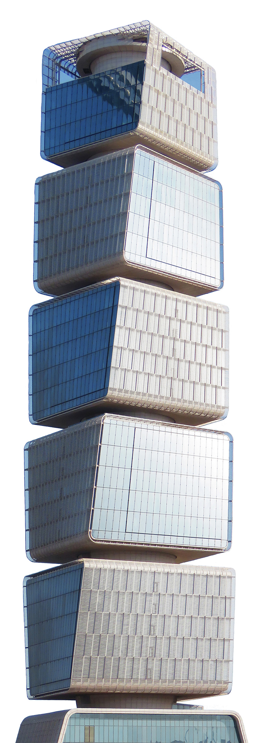
Over the last few decades, the Republic of Azerbaijan has seen its capital city of Baku transform into a modern metropolis defined by an ever-changing skyline that features some of the most eye-catching architecture in the world. The recently completed Ministry of Taxation Tower, with its signature form of stacked cubes suspended from a circular central core, is the latest addition to the growing number of the city’s landmarks.
Commissioned by the Azerbaijan Ministry of Economy, the 168 m, 32-story-tall tower comprises approximately 30,000 sq m of commercial office space. The building’s futuristic design and location within a high seismic zone created several challenges for the development team, which included FXCollaborative as the design architect, Tekfen Construction as the design-build contractor, and Thornton Tomasetti as the structural designer. Thornton Tomasetti was retained by Tekfen to provide structural engineering and construction services from the design phase and throughout the construction period.
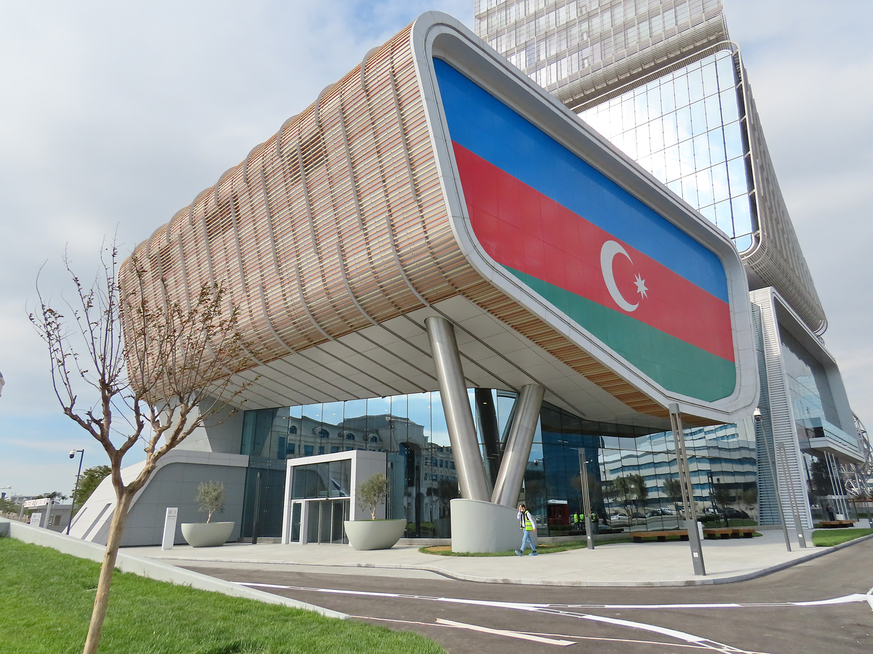
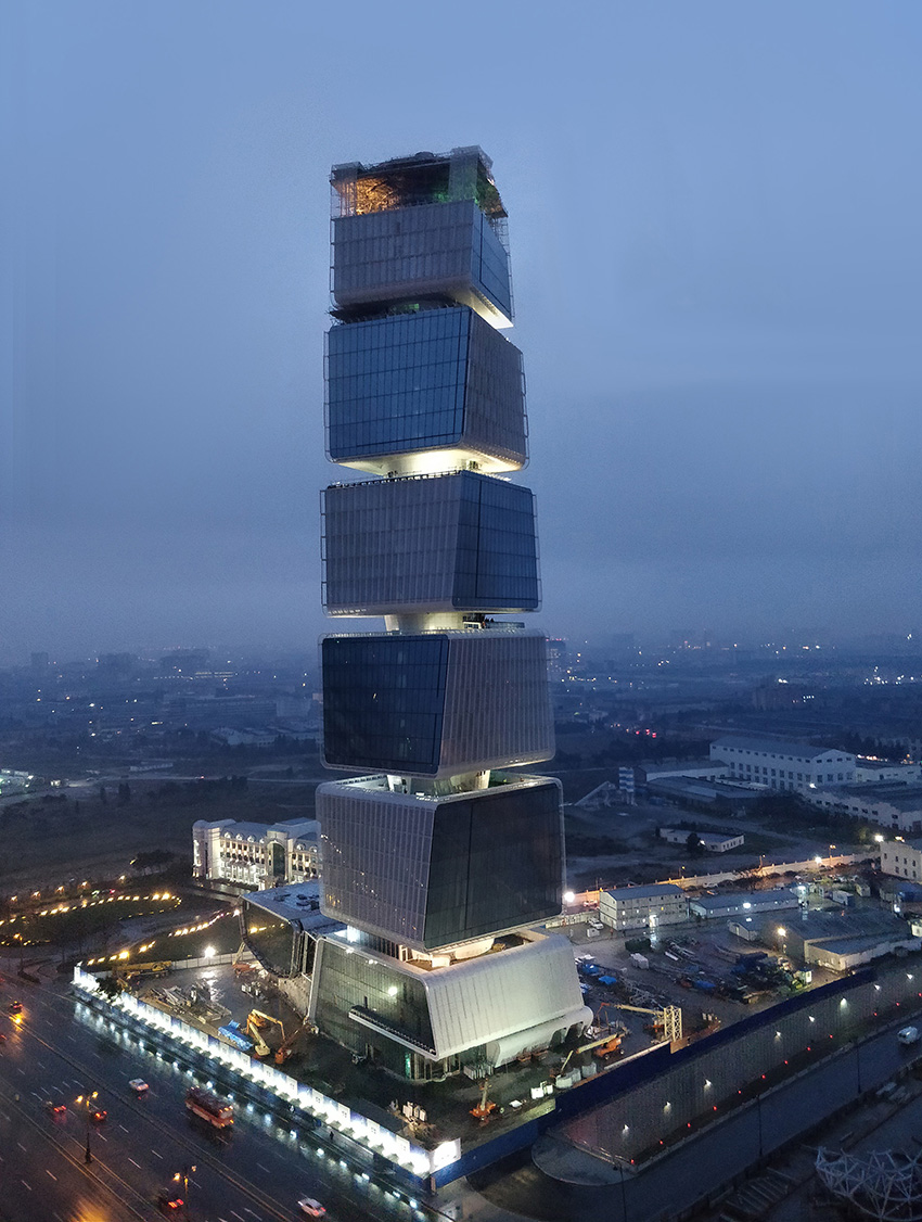
The tower’s striking architecture was achieved by a series of 8.4 m tall, column-free spaces located every six floors that serve as outdoor green areas for tenants. This creates an impression of stacked and rotating cubes that seemingly float on top of each other. The podium houses a 400-seat auditorium, boardroom, cafeteria, and winter garden at grade. This public plaza connects the new ministry tower to the neighboring, original mid-rise ministry building.
The auditorium is a three-story structure that is linked to the adjacent tower by two pedestrian bridges on level 2. The main entrance is below the sloping seats, resulting in a dramatic focal point for the plaza.
The tower sits at a critical juncture along Heydar Aliyev Avenue, which connects Heydar Aliyev International Airport to downtown Baku. There is also a subtle bend in the avenue, which allows for expansive views to and from the tower. This sightline served as a guiding principle when designing the building’s shape. Its rotating form not only gives tenants amazing city views but also helps improve solar performance.
Seeking concrete solutions
Because concrete is the predominant building material in Baku, the tower features a circular reinforced-concrete core that serves as the main gravity and lateral force-resisting element. Elevator shafts, egress routes, and mechanical systems shafts are housed within the core, allowing for greater flexibility and making it more suitable for office use. The floor framing is also reinforced concrete.
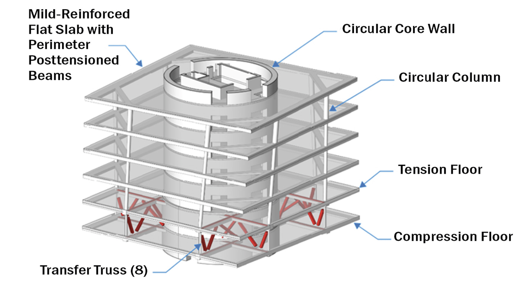
The building’s exceptional form of stacked cubes hanging from the central core demanded an innovative solution that included column-free floors between each cube, which required a hybrid transfer system. The dimensions of the square floor plates vary from 33 m per side at the base to 27 m per side at the top. Typical floors are supported by two sloping columns at each side of the floor plate, totaling eight 550 mm diameter circular columns per floor.
The design also features posttensioned perimeter beams that cantilever up to 9 m at the corners. Reinforced-concrete slabs, 200 mm thick, span from the core to the perimeter beams.
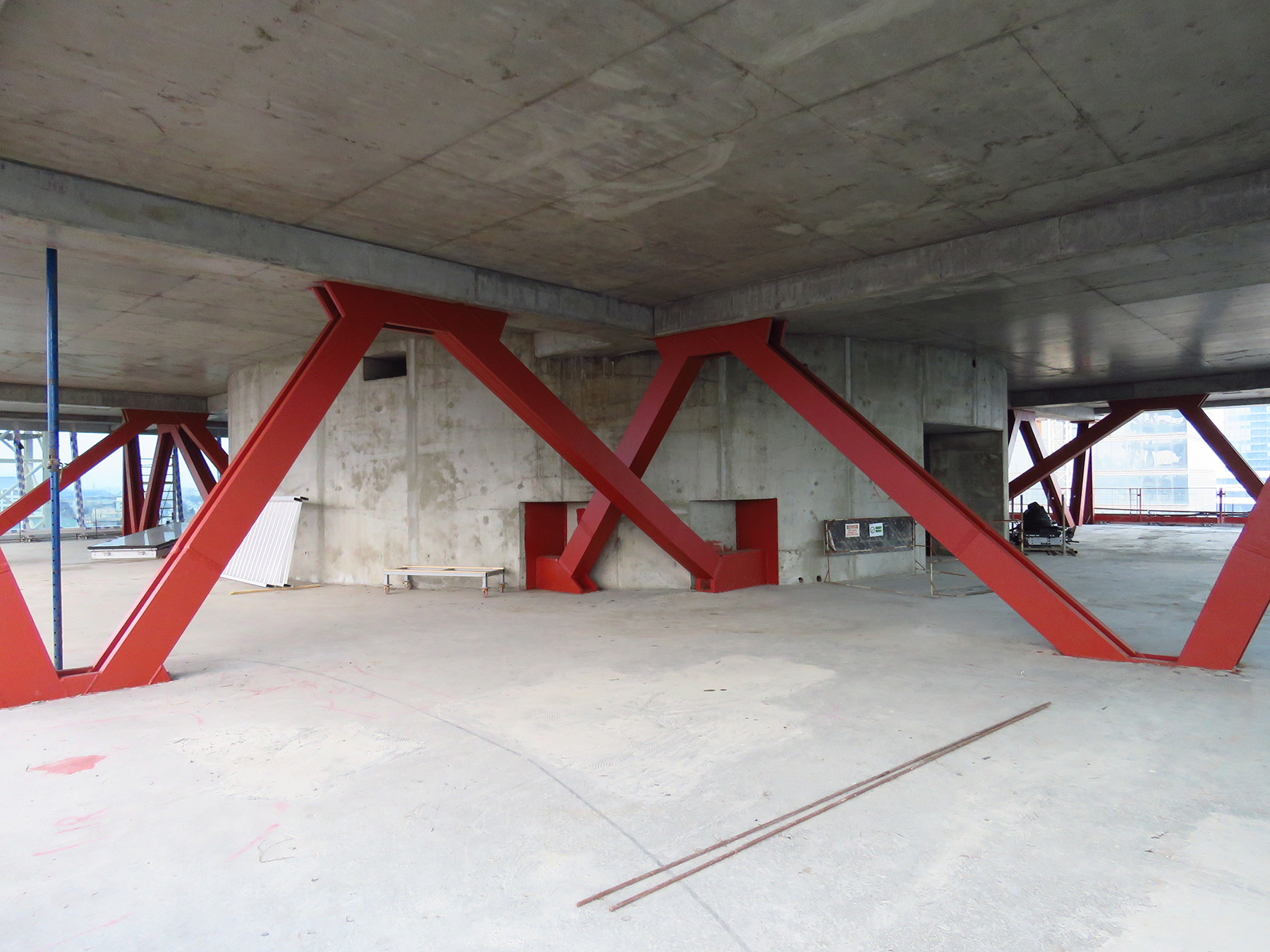
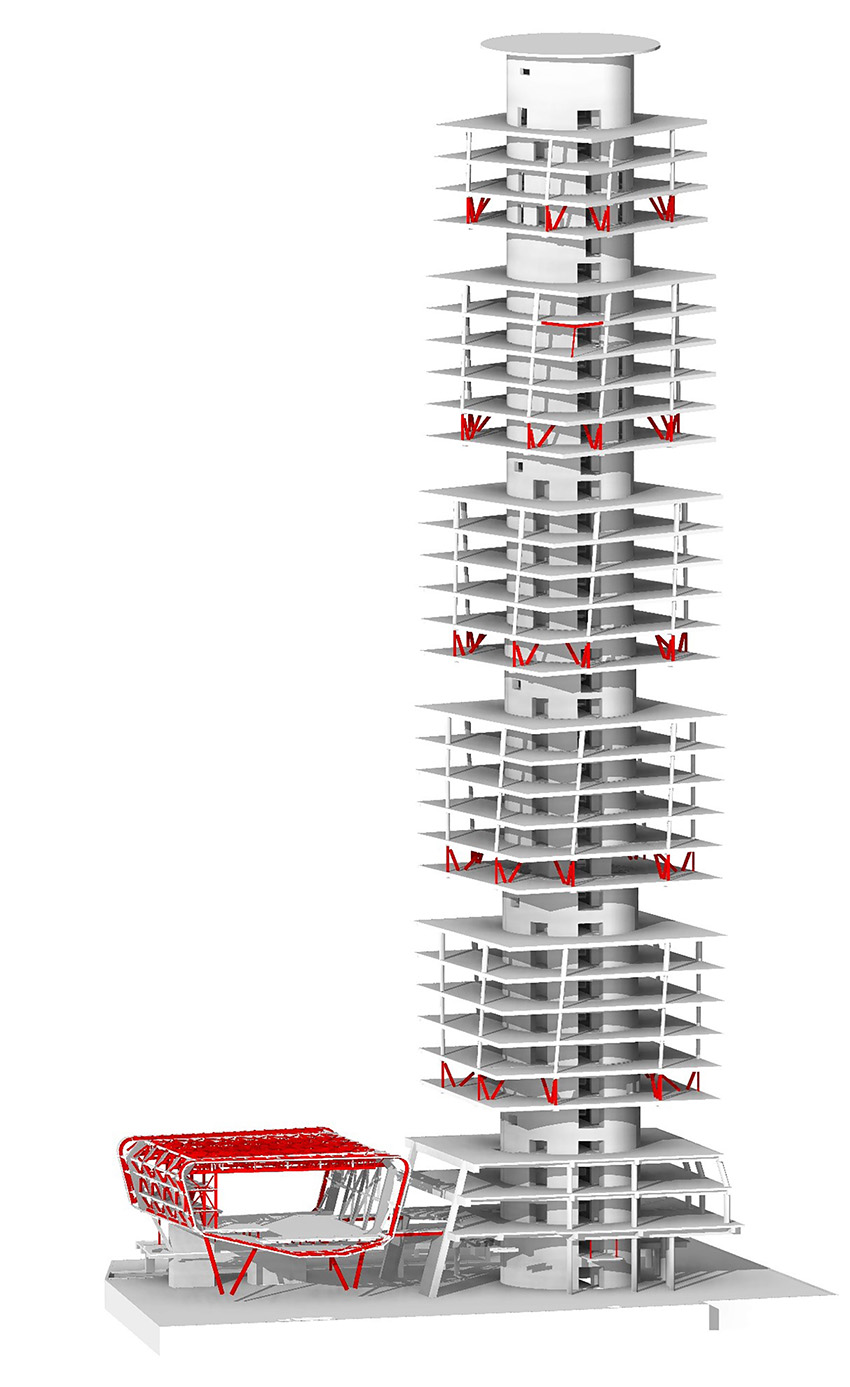
The lower two floors of each cube act as part of a transfer system that picks up the discontinued perimeter columns at every sixth level. One-story-tall, approximately 10 m long structural steel trusses divert the vertical column loads back to the central core wall; basically, one truss picks up one column.
The foundation system comprises a combination of a deep, cast-in-place reinforced-concrete piled raft under the main tower and a raft system for the surrounding podium. The thickness of the raft’s concrete mat varies from 800 mm beneath the podium to 3,500 mm for the tower mat. The piles measure 1,500 mm in diameter and reach a maximum depth of 42 m. They were all designed as friction piles with no end bearing capacity because of extensive amounts of clay in the soil.
The framing of the below-grade parking level and the ground floor is a one-way, reinforced-concrete slab with infill reinforced-concrete beams and posttensioned beams and girders between columns that are typically spaced at 16 m. The auditorium was framed primarily in structural steel to create a long, column-free space inside the auditorium. A composite slab provides the auditorium’s gravity support while a combination of braced frames and trusses constitute the lateral force-resisting frame of the space.
All structural components were sized according to internationally accepted codes such as International Building Code 2012 and ASCE/SEI 7-10, Minimum Design Loads for Buildings and Other Structures. In addition, local Azeri codes were referenced for compliance with the local building approval process.
Finding a hybrid answer
During the design phase, various transfer system options to support the floating cubes were evaluated. The inherent twist in the building’s geometry meant that the touchdown points of the perimeter columns would rotate along the building height. A typical “pass through” truss, or wall through the core — as used in traditional buildings with outriggers — would rotate along the building height and interrupt any sort of regular grid within the core wall. Therefore, a creative solution was needed to maintain efficiency within the core.
One of the options considered was an all-steel approach with both vertical steel trusses terminating at the face of the core as well as in-plane hoop steel trusses within a composite floor. Although this was by far the lightest option, the unit price of structural steel at the time made it too expensive.
Another option was a system relying entirely on reinforced concrete, which had the lowest baseline price. But such an inevitably heavy system would have required extensive shoring because each transfer system would have needed to be shored by the floors below. Moreover, this shoring would have to have been maintained in place throughout the construction process, impacting the amount of work that could be done in the floors below each newly cast transfer system.
Based on the insights gleaned from these studies, a hybrid system was selected. The final system included eight structural steel trusses centered on each reinforced-concrete column of the tower, with two floor slabs that are tied to the top and bottom chords of the trusses. After a series of coordination rounds with the project architect, the trusses were placed in tandem at the corners on the affected floors.
Because this system resists the chord forces within the concrete slabs, it was possible to effectively decouple the transfer system from the concrete core. As a result, all overturning moments induced into the transfer system from the aggressive cantilever were resolved within the slabs themselves, with tension and compression rings developing within the slabs that are connected to the trusses. This is similar to how large-scale stadium roofs employ compression and tension rings to maintain stability.
It was a solution that allowed the transfer system to rely on the core for only the vertical load transfer. In essence, the bottom two floors of each cube form a self-sustaining hoop system with a massive hole in the middle.
The self-sustaining nature of the system, however, does assume that all column loads are equal and, therefore, create restoring forces that are in equilibrium to one another. Due to the weight of the concrete slabs, the self-weight demand of the floors above constitutes most of the demand. Any unbalanced live loading that creates additional loads is easily mitigated by relying on the core to provide minimal restoring in-plane resistance.
As mentioned previously, the hybrid solution offered fewer construction sequencing challenges than the other options. The transfer system at the base of each cube — the trusses as well as the compression and tension floors connecting to the truss chords — required shoring until both slabs were hardened and gained full strength.
Therefore, it was imperative to reduce the weight of the system itself. This was achieved through the hybrid solution, which allowed shoring to be limited to a single cube below rather than multiple cubes, which the heavier, all-concrete options would have required.
Addressing high winds and seismicity
The lateral force demand for the tower is considerably high due to Baku’s unusually harsh wind environment coupled with moderate to high seismicity. Design wind speeds for a 50-year event there reach nearly 53 m/s, and the site classifies as Seismic Design Category D with site class D soil per ASCE 7-10.
To accommodate the wind loading, wind engineers at RWDI conducted a high-frequency, force-balance test to determine the structural wind loading characteristics for the tower design and predict wind-induced accelerations at level 30, the top occupied floor. Wind-induced acceleration criteria were set in accordance with the requirements of the International Organization for Standardization, headquartered in Geneva. Effective wind static forces were used to determine the demands in the core wall system at ultimate conditions as well as to estimate overall deflection and inter-story drift.
What’s more, for a tower with this height within seismic category D, ASCE prescribes a dual system consisting of a reinforced-concrete special shear wall with a special moment frame as the only lateral system allowable. But because of the lack of continuous perimeter columns, a dual system was impossible. To verify the building’s performance during a potential seismic event, the design team used a performance-based design approach that relies on the procedural guidelines outlined in ASCE/SEI 41-17, Seismic Evaluation and Retrofit of Existing Buildings and the Tall Buildings Initiative of the Pacific Earthquake Engineering Research Center, based at the University of California, Berkeley.
The performance-based design approach involved a nonlinear response history analysis using earthquake records and post-yield structural element properties to analyze and guide detailing of the core wall. For example, compression and shear stresses around the pockets in the wall — where the steel transfer trusses are supported — were closely monitored to ensure proper confinement of these regions.
A concrete strength of 50 MPa was used throughout the entire building height, with circular core walls varying in thickness from 1.5 m at the base to 0.6 m at the top of structure. The internal walls around the elevator shafts are designed with a constant thickness of 400 mm.
Results from the performance-based design analysis revealed efficient behavior under the maximum considered earthquake level. Compression strains were observed to remain well below crushing demands while tension yielding of the reinforcement was largely localized to the upper portions of the tower. This behavior was anticipated, considering the core wall acts as a bearing element and takes the full gravity demand of the tower, thereby resisting any net tension at the base of the building.
As expected for a coupled-wall tower, the main energy dissipation elements were the coupling beams, or link beams, between wall piers. Most of the beams were detailed with conventional reinforcement since rotations were less than 2%. Diagonal reinforcement was provided only where demands or rotations were relatively higher.
Framing the auditorium
The 20 m tall auditorium structure covers a footprint of 20 m by 25 m. Its floor system is a 150 mm thick composite slab supported by gravity beams spaced at 3.3 m. To create a column-free space that could seat 400 people, the design team selected 1.6 m deep steel trusses running in the north-south direction. The trusses were spaced at approximately 5.5 m apart and connected to the roof.
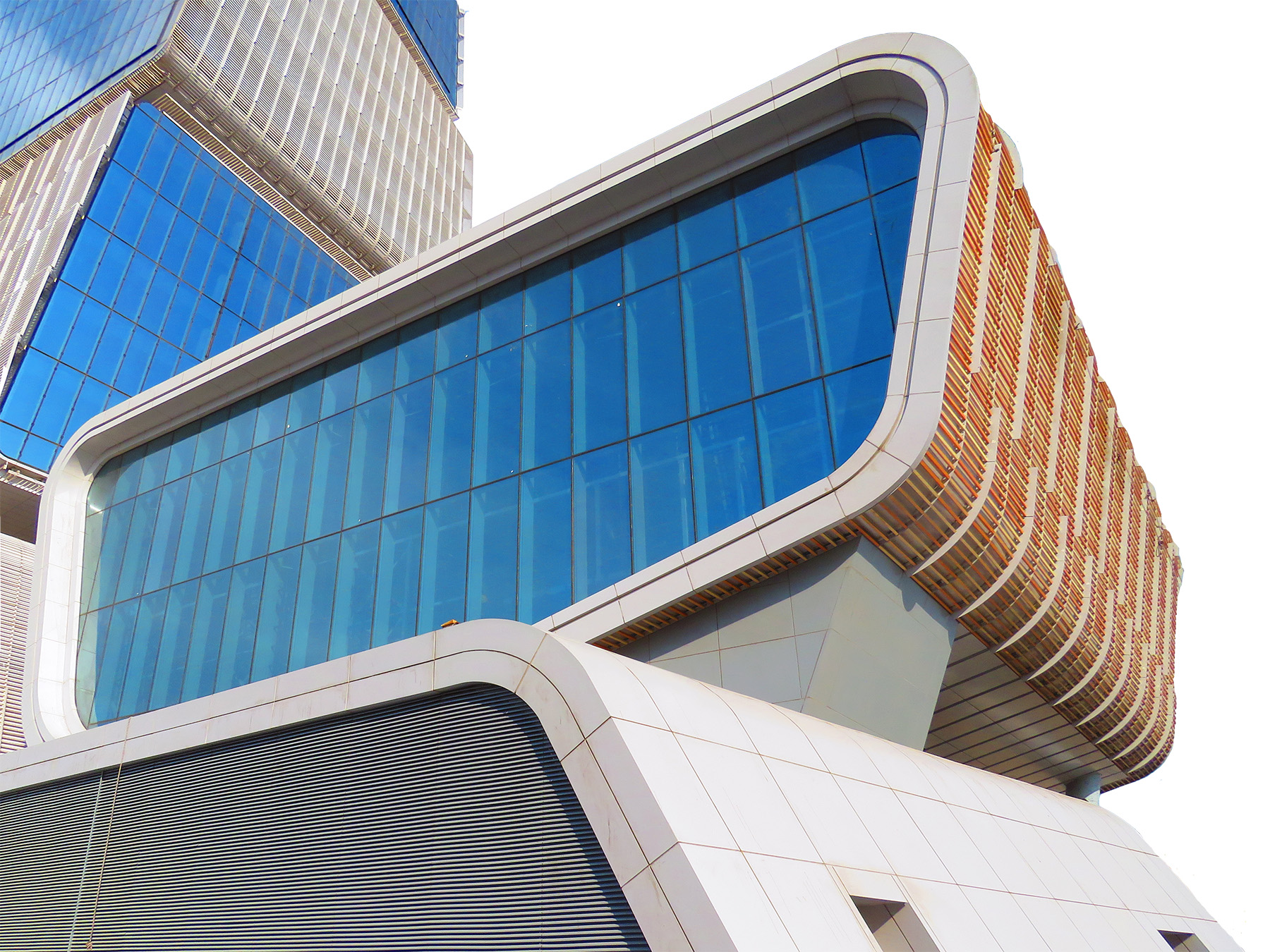
At the east and west ends of the structure, 25 m long trusses were built up into a box frame measuring 1,250 mm by 550 mm. These frames are supported by four sloping columns on the south side; to the north, they are carried by approximately 5 m tall reinforced-concrete elevator shaft walls. Braced frames were used for the lateral stability of the structure. A steel bridge connects the auditorium structure back to the tower, with an expansion joint provided between the tower and the auditorium to allow for independent movement during a severe seismic event.
Completed in 2021, the Ministry of Taxation Tower has become a new national landmark for Azerbaijan. Using advanced structural analyses, a state-of-the art column transfer system design, complicated construction sequencing, and a seismic-performance-based design, the project team was able to overcome the obstacles and bring this unique structure to life. The Ministry of Taxation Tower will serve as a focal point on Baku’s skyline for years to come while the city continues to redefine itself.
Hi Sun Choi, P.E., LEED AP, is a senior principal, Onur Ihtiyar, P.E., LEED Green Associate, is a vice president, and Nickolaus Sundholm, P.E., is a senior project engineer in the New York City office of Thornton Tomasetti.
Owner: Ministry of Taxation of the Republic of Azerbaijan
Design/build contractor: Tekfen Construction, Istanbul
Structural design: Thornton Tomasetti, New York City
Wind engineer: RWDI, Guelph, Ontario
Mechanical systems: Kiklop Design & Engineering, Istanbul
This article first appeared in the January/February 2023 issue of Civil Engineering as “Towering Twists.”


