
By Marc Percher, P.E., M.ASCE
Civil engineers are used to constructing buildings and other structures on top of dirt, but with sea levels rising and the cost of creating new land becoming more economically and environmentally challenging, placing nearshore structures with permanent moorings over water has become increasingly advantageous.
For example, in instances when a structure must transfer a large amount of heat out of a system to keep equipment cool, as is sometimes the case with industrial processes, a floating structure can have significant advantages.
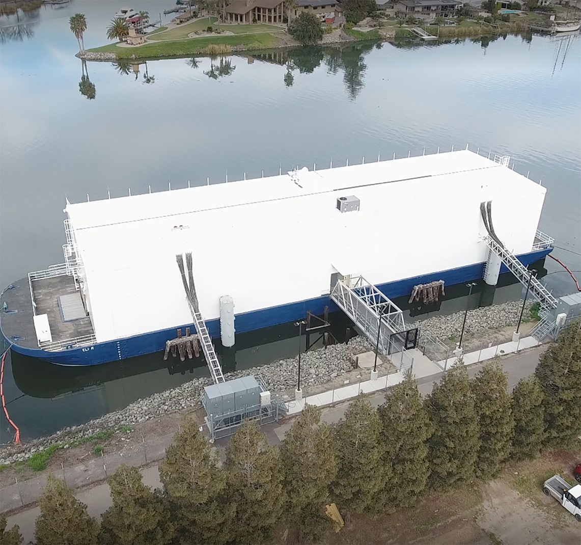
For environmentally sensitive areas or greenfield sites that would require significant land reclamation or dredging, floating structures can reduce the cost and footprint of landside ground preparation and make projects economically viable. Even for conventional structures, such as fire stations, there can be economic advantages to being built using floating construction, especially in areas where landside space is limited or expensive.
Basically, with limitations on budgets and available land, it is time for civil engineers to think beyond building on dirt and begin to understand and embrace the benefits of buoyant structures and how to moor (structurally tie) them to land.
Governing bodies
When designing and building conventional structures, civil engineers are used to balancing the needs of the owner with those of the reviewing agencies, which may include building officials and other regulatory agencies. For floating structures, an additional player added to the mix is the classification society. Classification societies are organizations that typically review the design, construction, and maintenance of commercial vessels — including nearshore floating structures that are permanently moored — certifying that they have been built to code. Classification societies also provide due diligence for the companies that insure these vessels.
Nearshore floating structures that are permanently moored to a landside-fixed component fall within multiple jurisdictions, each with their own criteria, including the classification society and landside regulators, namely the authority having jurisdiction, as well as possible other stakeholders.
Early discussions between the landside AHJ and the classification society to determine jurisdictional limits is critical to ensuring that code and class requirements are met for every part of the structure.
Typically, the jurisdictional limit for the classification society is the face of the vessel, but it may also include the permanent mooring from the vessel to the landside foundations.
AHJs for landside construction will evaluate the mooring foundations, but they may also examine the means of access/egress and any other supporting structures.
When toxic or hazardous substances are involved, additional regulations and criteria may also apply and will be considered in the structure’s design and construction.
The design team should develop a detailed set of documents, including the concept of operations, functional requirements, and basis of design early in the project development phase.
These documents are paramount to obtaining early buy-in from stakeholders and ensuring that the final design meets all requirements.
Permanent mooring loads
Landside structure loading is well covered by ASCE 7 Minimum Design Loads and Associated Criteria for Buildings and Other Structures. However, for marine structures, in general, it is often necessary to reference outside guidance documents when considering mooring, berthing, waves, and other conditions. World Association for Waterborne Transport Infrastructure (commonly referred to as PIANC) working groups, U.S. Department of Defense Unified Facilities Criteria, and other international guidance documents serve as reference tools for determining loads on floating structures.
But many of these standards were developed for the temporary mooring of ships, not permanently moored floating structures. When a vessel calls at a berth, it can also move off the berth in advance of a large storm or far-field tsunami. However, a permanently moored floating structure cannot be easily moved. As such, the design for these floating structures must factor in more extreme environments.
Determining wind loads on structures typically involves the use of mapped values with return periods of 300 years for Risk Category I, 700 years for Risk Category II, 1,700 years for Risk Category III, and 3,000 years for Risk Category IV, according to ASCE 7-22. Marine structure moorings are typically designed for one or more events that have return periods that are significantly lower than those for wind loads on land-based structures. Examples of design criteria used to determine the wind loads include:
- 60 knots wind: Oil Companies International Marine Forum Mooring Equipment Guidelines 4.
- One-year operational (with calling vessel) and 100-year survival case: Recommendations for the Design and Assessment of Marine Oil & Petrochemical Terminals, PIANC WG 153 Rev B.
- 100-year return period storm for permanent moorings: Unified Facilities Criteria 4-159-03 Moorings (March 12, 2020).
Designing for storm events that combine wind, wind waves, and the current ASCE 7-prescribed return periods is too extreme to be economical; therefore, it is important to differentiate between wind loads on structures versus environmental loads on vessels. Wind load on the mooring system is applied only to the surface area of the fixed or mooring structure, whereas environmental loads (mooring loads) apply to the windage and subsurface sail areas of the vessel, which are typically much larger areas.
The design team should conduct a site-specific metocean study (examining tide, wind, wave, current, tsunami, etc.) to refine the design environment values. Available data sets near the project site may be limited in duration such that return periods in excess of 100 years are not statistically valid. Where facilities are exposed to swell waves, the team must consider the period of the vessel and mooring system, as even small swell waves can cause significant resonance if they are at the period of the floating structure (typically 10-30 seconds).
If the design requires rope lines or chains as part of the mooring system, it is important to maintain a philosophy of failure modes (determining the sequence of failures) wherein the lines will break (or winches may render) prior to failure of the mooring anchorage hardware, which should fail before the supporting structure. PIANC WG 153B provides good guidance on appropriate safety factors and approaches to maintain this balance.
For more extreme events like earthquakes and tsunamis, the design must satisfy the return periods specified by the AHJ because the classification societies do not have design criteria for these events.
Tsunamis in particular can be challenging to design for because there is insufficient data to get an accurate statistical basis for an appropriately sized return period event. Far-field tsunamis are usually caused by subduction zones, but near-field tsunamis can be generated by subsea landslides that may not be related to earthquake events.
Determining the proper design for tsunami events requires a multidisciplinary team, including a geologist or geotechnical engineer, to calculate a safe amount of soil movement. A coastal engineer should be part of the design team as well to model the induced tsunami wave within the basin where the structure will be moored. The data created can be input as time history wave data in subsequent vessel hydrodynamic and structural analyses as described below.
Selection of appropriate performance objectives for tsunamis and earthquakes can also lead to more economical designs. Mooring systems must perform elastically for storm events, as any damage is likely to lead to low cycle fatigue and unzipping of the system. However, earthquakes and tsunamis are such rare events that more damage may be acceptable, depending on owner, AHJ, and classification society approval.
ASCE 61 Seismic Design of Piers and Wharves provides good guidance to help determine acceptable amounts of damage; the standard can also be applied to tsunamis. During a tsunami the mooring system itself should be kept elastic — again, due to low cycle fatigue and the pseudo-static nature of tsunami currents. However, noncritical elements like gangways, fenders, and other peripheral structures can be sacrificed if the floating structure is held in position on-site. In some cases, it may be more economical to design for failure of the primary mooring system and include provision for a more flexible secondary system, such as a catenary mooring.
Analysis methods
Analysis of permanent moorings of floating structures is also inherently more complicated than landside or nearshore-fixed floating structures because floater motions must be captured using appropriate hydrodynamic modeling software. This software determines the full dynamic six degrees of freedom response (surge, sway, heave, yaw, roll, and pitch) of the floating system. These hydrodynamic models evaluate floating structure motions throughout long-duration events like storms or highly dynamic events like tsunamis.
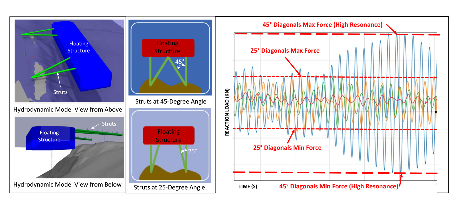
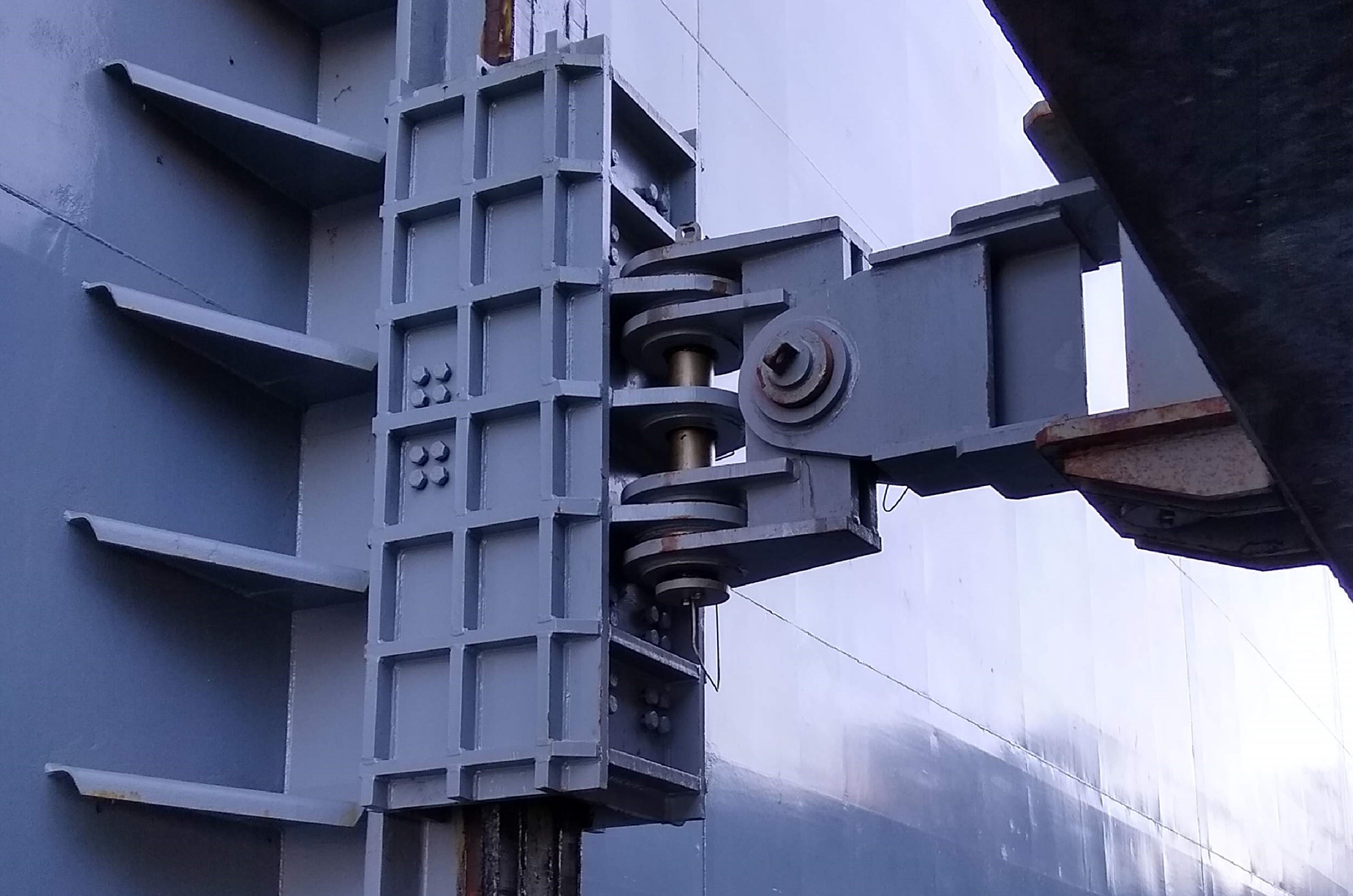
Often, iterative evaluations of a system’s effective stiffness are required between these hydrodynamic models and any structural models used to design the permanent mooring structure itself since the structure and mooring system can be subject to resonant events. The image above shows an example of a strut mooring system for which a 45-degree-angled brace strut resulted in significant resonance and high loads, whereas shifting the angle to 25 degrees resulted in a longer system stiffness and reduced loads.
The design team should input loads or displacement data generated from hydrodynamic modeling into structural modeling software using appropriate load combinations (again, PIANC WG 153B and UFC give good guidance on load and resistance factor design criteria as well as classification society documents). Keep in mind that each load output may have peak values that are not concurrent with the other peak loads from each degree of freedom.
To return to the strut mooring example, each of the four mooring system connection points to the floating structure produced six DOF displacements/rotations; therefore, each single peak value of a single DOF resulted in 23 concurrent DOF outputs. When considered with LRFD combinations, the total number of cases to be considered snowballs quickly.
Earthquake loads on floating structures (of any type) are best considered on a displacement basis because the floating structures are inherently base isolated and resonate at a period of 10-30 seconds compared with the 0.5-2-second period for typical marine structures. As discussed in the 2016 ASCE Ports conference paper “Effect of Moored Vessels on the Seismic Response of Structures” by R. K. Iwashita et al., vessel-structure interaction is likely to dampen the structural response.
Where grippers, guides, or other direct mechanical connections occur, they must accommodate the landside displacement of the fixed structure relative to the floating structure, which should be fitted so that it is not displaced. These elements can also be designed with fuses that enable transfer of service (storm, berthing, or other events) but release during seismic responses.
Detailing
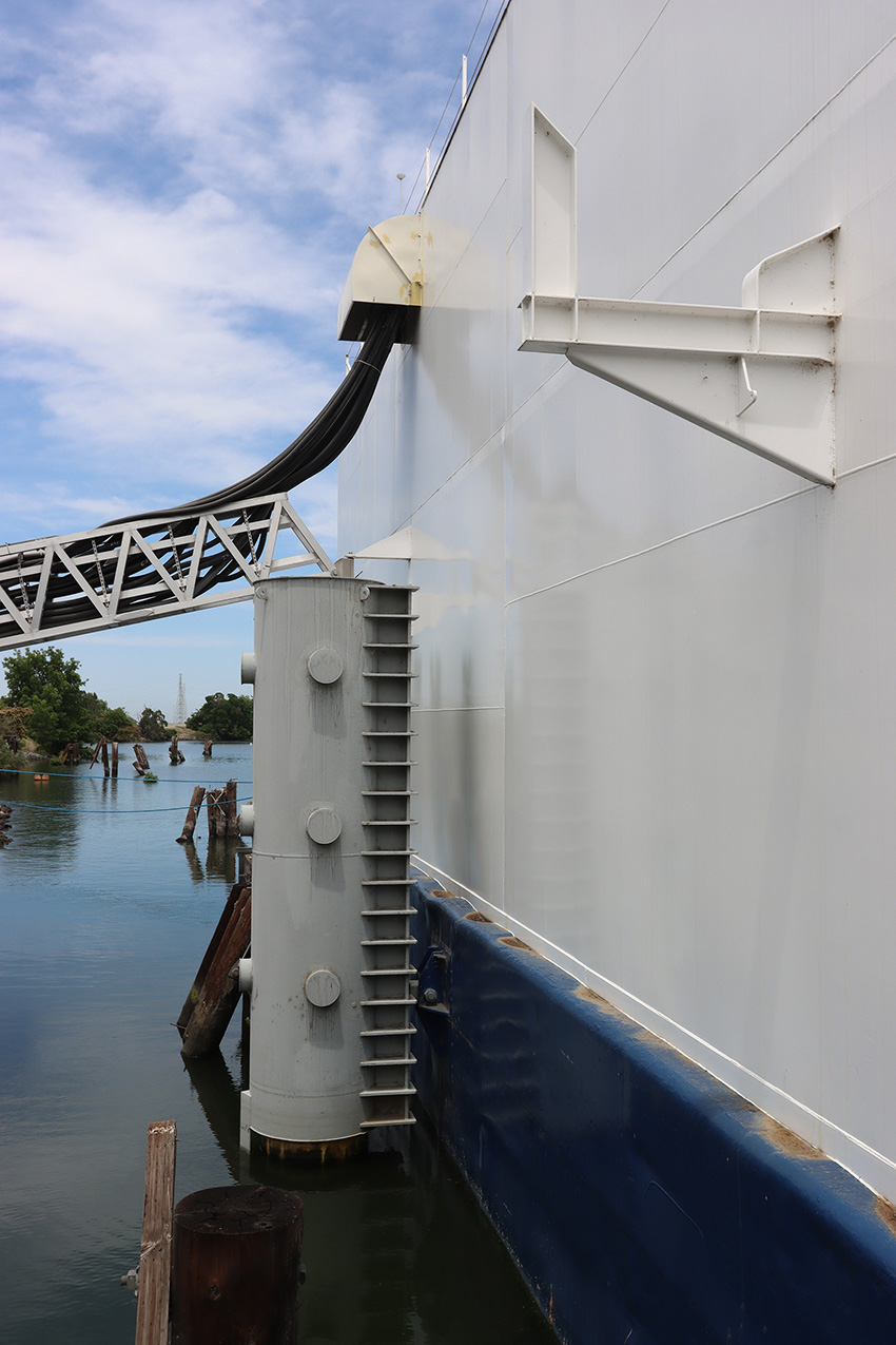
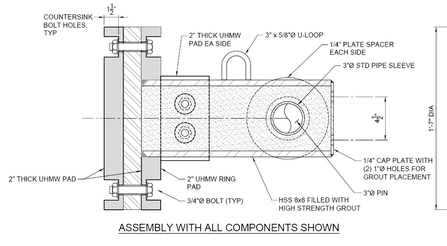
Detailing for nearshore-fixed moorings of floating structures entails balancing flexibility for the large range of motions with the fatigue life of the system. To satisfy this balance, it is often necessary to incorporate into designs specialized mooring systems to floating structure connections such as chain tensioners, grippers, guides, hinges (single or universal joint), spherical bearings, or other types (see images above). Concentrating movement within the manufactured hinge or bearing elements can help reduce the impacts of fatigue.
Pipe section members and welded connections improve torsional responses and fatigue life as outlined in the American National Standards Institute/American Institute of Steel Construction 360-10 Specification for Structural Steel Buildings and the American Petroleum Institute’s 2A-WSD: Recommended Practice for Planning, Designing, and Constructing Fixed Offshore Platforms.
Where larger assemblies or trusses are used as the mooring system, calculations for the fatigue life should encompass loading during shipping to the site. If the connection elements are intended to slide, as is the case with guided elements, ultrahigh molecular weight polyethylene facing should be used to reduce friction and accommodate any replaceable wearing surfaces.
Care must be taken so that these elements can be maintained and replaced without having to disconnect the mooring. Conventional rubber fenders are also an option, but the service life of these fender units may be significantly reduced — from 15 years to five years — due to the constant motion.
Consideration should also be given to the design life of the floating structure itself because steel floats may need to be dry-docked every 15-25 years, whereas concrete floats may have longer life spans and therefore require connecting elements that also last a long time.
Conclusion
While the economics are improving and the use of floating structures is increasing, they represent a civil engineering challenge that requires specialized knowledge and a highly versatile multidisciplinary team. Creativity and meticulous strategizing are key to ensuring that the mooring system tying the structure to the shore can survive the full range of design events while remaining readily constructable and cost-effective. When the design team addresses the issues stated above, it is possible to solve these complicated problems and ensure that a rising tide raises all structures.
Marc Percher, P.E., M.ASCE, is a senior engineer at COWI in its Oakland, California, office. He has more than 20 years’ experience in structural engineering design and analysis.
Learn more
Marc co-teaches the ASCE on-demand course Seismic Design of Piers and Wharves per ASCE 61 (24 PDHs).
This article first appeared in the September/October 2023 print issue of Civil Engineering as “Design of Permanent Moorings for Nearshore Floating Structures.”
