
By Gary Conner, P.E., S.E., Devin Altman, P.E., M.ASCE, Scott Anderson, Ph.D., P.E., M.ASCE, and Brian Collins, P.E.
What do you do when a massive landslide closes off the road to the tallest mountain in North America? Meet the Pretty Rocks Bridge, a daring work in progress that will reopen access to the interior of Denali National Park & Preserve.
Denali National Park & Preserve in Alaska is slightly larger than the state of New Hampshire. The park is served by the single-lane 92 mi long gravel Denali Park Road, which is now closed at milepost 45 due to the Pretty Rocks landslide. This is not a swift landslide like an avalanche, an event that is quickly over; its movement is more like a glacier, a feature of the landscape that has existed here for more than a century.
The section of road that crosses the landslide was constructed in 1930, and this section historically required only minor grade rebuilding maintenance every few years due to the slow-moving landslide.
However, conditions began to change. Higher local temperatures accelerated melting of the permafrost. Eventually, the road grade movement reached more than a half inch per hour, and maintenance crews could no longer bring in material fast enough to replace the material lost to the slide. The old ways of maintenance were no longer sustainable.

What’s more, a major economy — an estimated $1 billion per year tied in part to cruise ships and ports — had grown around the road. Something had to be done. So, Denali National Park, the National Park Service, and the Western Federal Lands Highway Division of the Federal Highway Administration — the agency supporting the park and NPS in maintaining public access — led an investigation of alternatives to ensure that the heart of the park remains accessible long-term.
The alternatives to keep the road open included major work on the existing alignment or new alignments that would bypass the site. However, after study by the NPS and WFLHD and a geotechnical risk assessment led by Jacobs and BGC Engineering, it was decided that the best option would be to bridge the landslide on the existing road. This option was considerably less impactful to the environment, less costly, and less risky, and the quickest option for fully reopening the road.
Preliminary bridge design
The project team began preliminary design by gaining a detailed understanding of the geology so that the stability of potential abutment locations could be determined and the bridge alignment established. The landslide occurs in the weaker and colorfully weathered volcanic rock in the center of a tight fold, which was a new discovery. This colorful exposure of folded and weathered rock is how the Pretty Rocks landslide gets its name.
The landslide has the characteristics of a rock glacier, wherein ice fills at least some of the rock and soil particle voids through which creep deformation occurs. Some landslide movement occurs on a basal shear surface, and some occurs within the body of the landslide. The site is not an empty chute, nor is it simple layered stratigraphy. Because of these factors, the landslide will continue to move, and new material will be sourced from above as the landslide retrogresses upslope.
The geotechnical investigation on each side of the landslide identified highly fractured and weak rock, clay seams, preferential pathways for water, and opportunities for ice wedge formation. The investigation also uncovered why the landslide is shaped like it is, with a long neck separating into two adjacent lobes at the valley floor 600 ft below. The landslide’s relatively narrow width is constrained by the stronger and more favorably oriented rock on either side of the fold, and this offers the potential for stable bridge foundations quite close to the margins of the landslide.
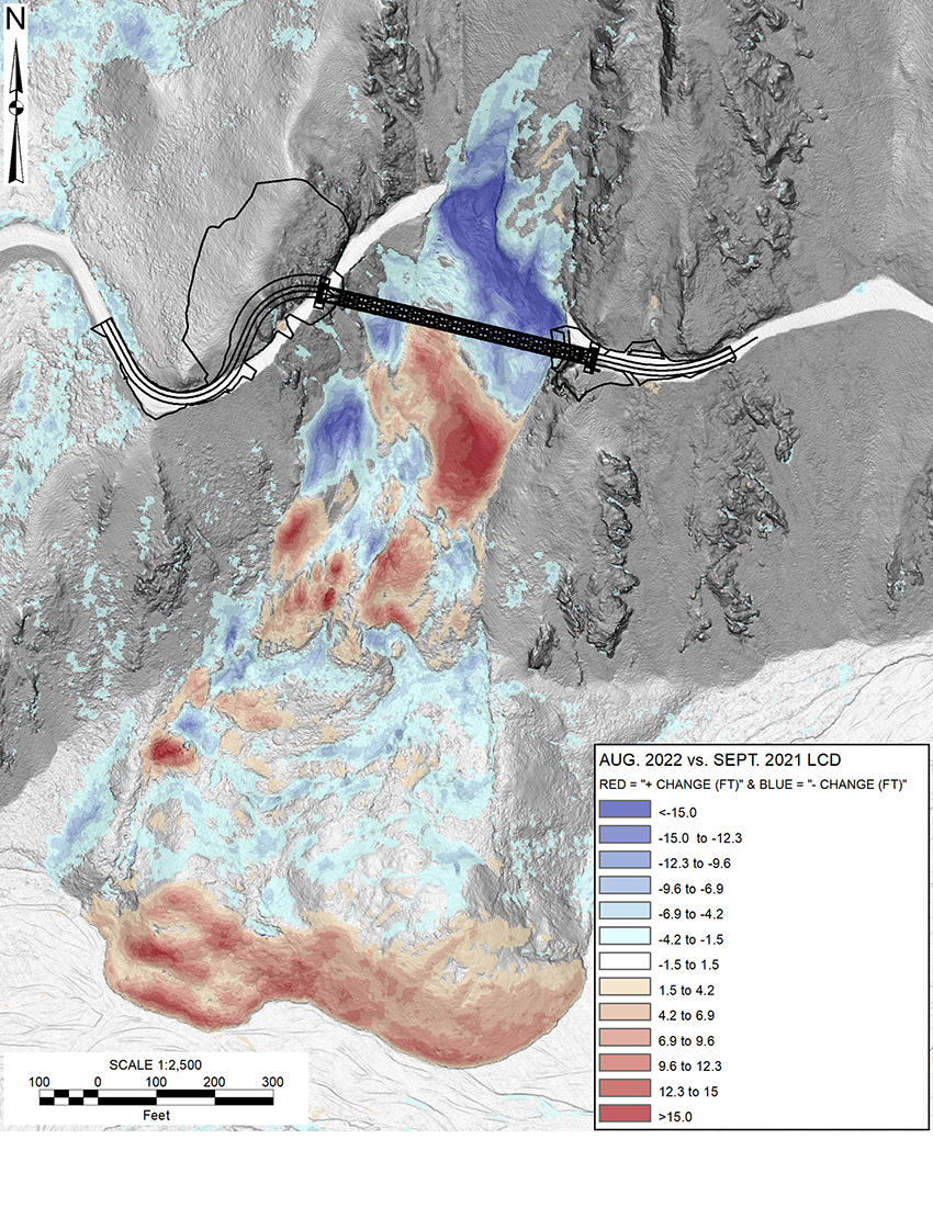
The project team mapped the geology using rock outcrop exposures and drilling investigations with televiewer logging of drill holes. The constrained lateral growth of the landslide was confirmed using aerial remote sensing and topographic change detection analysis in Cambio Earth software.
The investigations revealed diverse and complex rock formations and permafrost with significant ice content on both sides of the landslide. This information was used to create a 3D geologic model that was a valuable aid in the selection of abutment locations and for designing the foundations and rock cuts needed to provide access to the bridge abutments.
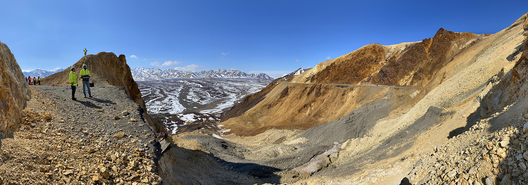
To avoid future slide movement and to keep the bridge length as short as possible, the west abutment needed to be located on an outcrop of competent material that was on a bearing tangent to the roadway alignment on the east side of the landslide, even though that meant a large cut would be needed for the west bridge approach.
On the east side, the bridge abutment needed to be on the current roadway because any cut above or fill below the existing roadway bench would have to extend for several hundred feet.
The primary challenge with the east abutment is the highly fractured rock containing ice layers up to 13 in. thick, 80 ft to 90 ft below grade. Such massive ice was not found in the rock beneath the west abutment, but ice was found in the soil and rock that had to be excavated to provide bridge access.
The primary design challenge on the west side was the many potential rock wedges that formed the cut slope and the subsequent requirement for strategically placed rock bolts that would have to be installed as the cut was made.
There were two elements to the design and construction of the abutments. The first was ground modification to build a stable abutment environment, and the second was the foundation design itself. On the west abutment, where the rock is basalt, the team installed a pattern of rock dowels below the abutment seat. These are not needed for global stability but were installed to protect against future temperature changes and continued slide movement.
On the east abutment, where the rock is fractured rhyolite with ice layers deep below ground, more was required. Rock dowels were not sufficient to secure the fractured rock face, so the team constructed a soil nail wall, with a similar pattern to the rock dowels except that the nail heads are connected with flexible wire facing. The wire facing was used in lieu of reinforced shotcrete because it is easier to work with, and it would not impound water or incur ice-wedging forces.
An additional requirement for the east abutment was the need to keep the ice in the rock formation frozen. This is important given the likelihood of increasing temperatures and changes to the grading due to slide activity and construction that will impact the location of summer thaw. To do this, the team installed 23 thermosiphons in an array to a depth of approximately 100 ft beneath the abutment.
Thermosiphons are passive heat exchange elements that are charged with carbon dioxide. They consist of evaporator and condenser units that bring cold winter air to depth in the warmer rock, where liquid carbon dioxide then evaporates and rises as a gas, only to condense in the cold environment aboveground, and drain to depth again.
The process is perpetual as long as there is sufficient temperature gradient. Temperature monitoring at depth has already been initiated, but the thermosiphons are within the area needed for the bridge erection, so they will not be charged until construction is complete.
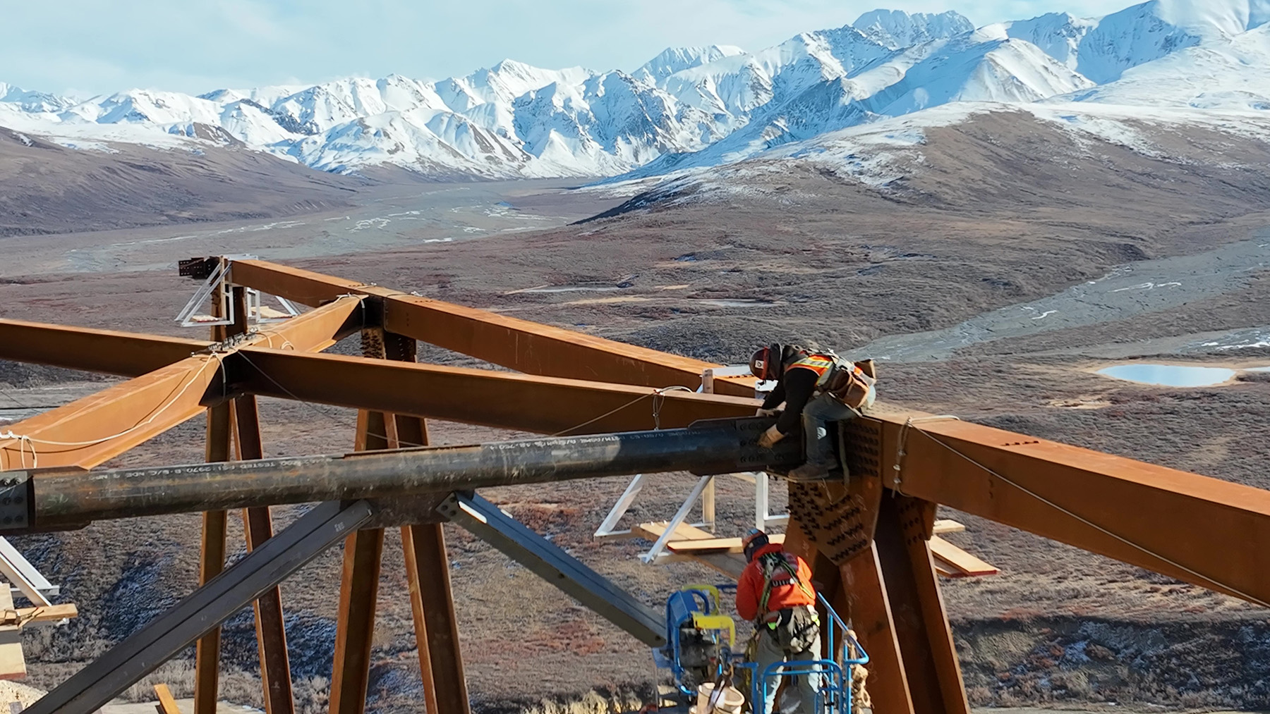
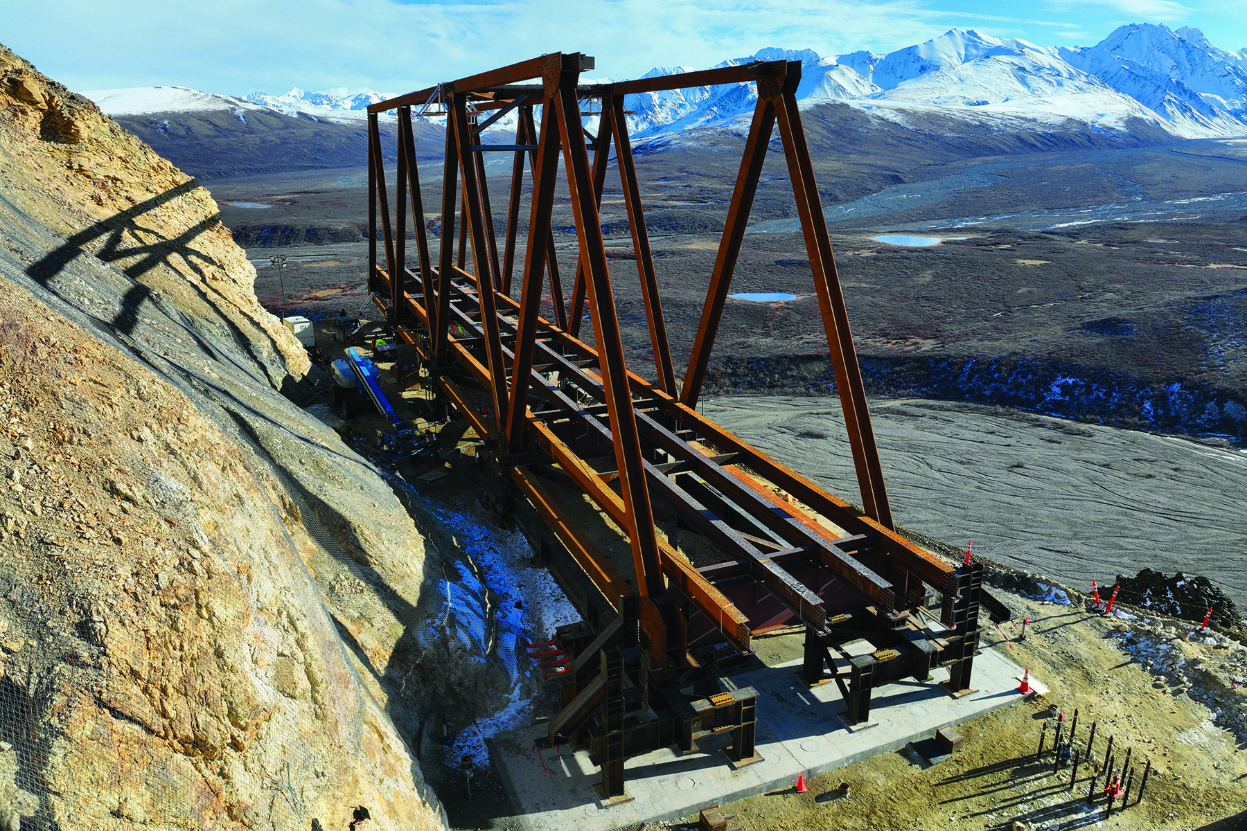
Due to the site conditions, the design team settled on a 475 ft single-span bridge. Given the roadway geometry, steep slopes on the east side, and the remote nature of the site, a steel truss was the logical bridge solution due to its long-span capacity, feasibility of erection, low weight, and easily shippable members and components. The team selected a weathering steel Warren Truss with a depth of approximately 50 ft and an 18 ft wide single-lane roadway.
Limited access for construction equipment at the site necessitates other special design features, including steel Sandwich Plate System deck panels with a urethane core, precast abutment elements that are post-tensioned together on-site, and micropiles and ground anchors installed with small footprint drilling equipment.
Of course, there are significant obstacles to constructing a bridge at this location. It is geologically complex, increasingly unstable, difficult to access, and has only a five-month summer construction window; but beyond all that, the site also has a very limited amount of level ground on which to work. Since the ground below the span is in constant motion, the project team could not employ temporary supports from below.
For these reasons, as well as the need to complete the design and construction as fast as possible, Granite Construction was brought on board early in the design process as the construction manager/general contractor to work through the numerous constructability and design challenges.
The 30% design plans used to initiate the CM/GC contracting process called for dual cantilever bridge erection proceeding from each abutment, with erection stays securing each cantilever at the abutments until they meet in the middle and with construction materials delivered to the leading edges by cable highlines.
Soon after the CM/GC contract was awarded to Granite, collaboration meetings were begun between designers and contractors. An early outcome of this collaboration was a suggestion by steel erection subcontractors KWH Constructors Inc., and their in-house engineering division Somerset Construction Engineering, to change the erection scheme and launch the bridge across the landslide. After evaluating cost, risk, and schedule for both launching and dual cantilever erection, in early 2023, the designers, the contractors, and WFLHD made the decision to longitudinally launch the truss.
Final design
As soon as the decision was made to launch the truss, the combined design and construction team began an integrated design and detailing process, with the structural, geotechnical, and construction engineers closely collaborating to rapidly solve the many challenges and accelerate the design, steel detailing, and fabrication processes using Building Information Modeling for Bridges.
Because of the urgency to restore access to large portions of the park and the short construction season at the site, acquiring steel and starting fabrication were paramount to beginning construction quickly.
As soon as the design team developed design details, the contractor modeled those details to provide timely feedback on the design, get a head start on fabrication drawing production, and allow the designer to perform early reviews. Within five months, the bridge design was advanced from 30% concept to 100% plans and specifications, with the truss modeled (in Tekla and Trimble Connect), the shop drawing detailed plans developed, and the steel mill material order placed.
Final design features
The truss superstructure is made entirely of structural weathering steel (ASTM A709 Grade 50W with some ASTM A588), including the lightweight sandwich plate system bridge deck. The main truss chords, gusset plates, endposts, portal and lateral bracing, floorbeams, stringers, and steel tube railing were all designed to be readily shipped by limiting their lengths to less than 50 ft.
 dit photo credit]
 Many of the truss gusset plate connections were designed and fabricated with ASTM A709 Grade 70W material (stronger than Grade 50W) to limit the superstructure weight as much as possible.
Top and bottom chords and the endposts are welded box sections, truss diagonals are welded H-sections, floor beams are welded I-sections, and the remainder of the sections are standard rolled wide flange, channel, and angle sections.
The project team chose isolation bearings for their ability to accommodate differential movement between abutments as well as to reduce the seismic loads to foundations and within the truss.
These bearings also include a fused bolt connection to the masonry plate to withstand significant wind loads but limit the transverse seismic loads within the truss. The bearing masonry plate is welded to steel embedments within the precast footing segments.
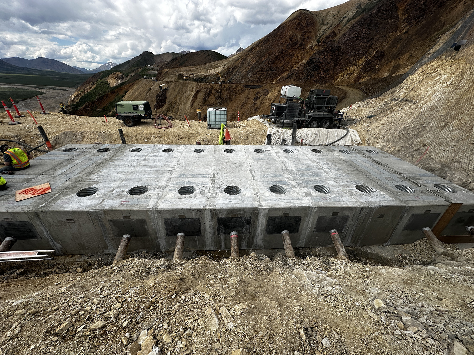
The foundations are composed of thirteen 4 ft × 4.5 ft × 15 ft precast reinforced-concrete modular blocks grouted and post-tensioned in the field. The blocks have steel connections to the vertical ground anchors and battered micropiles that extend into the rock approximately 40 ft. The micropiles and ground anchors are composed of a high-strength bar encased in grout within a steel casing. BGC and Jacobs collaborated to design the soil-structure interaction for the loads and spring properties that the native rock exhibits.
The abutment foundations have been designed for the wide range of construction and permanent loads they must bear, and although the forces will be larger at the east abutment, both abutment foundations have been designed with identical structural details for simplicity of work and material delivery to the remote bridge site.
A unique aspect of the foundation elements is that there are vertical ground anchors in tension and subhorizontal micropiles designed primarily for compression. One might expect the opposite, but the ground anchors stiffen the system by putting a large normal force on the interface between the footing and underlying rock, making horizontal load transfer more compatible with compression in the subhorizontal micropiles. After construction, the ground anchors and micropiles will provide long-term reinforcement to the rock beneath and adjacent to the abutments.
Designing for constructability
Constructability was a primary area of focus as the team finalized the preliminary concept for the truss. The schedule was tight and had to accommodate any loss of time due to space constraints. With this in mind, the project team decided early on to design the connections so that the structural bolt nuts would face the exterior face of the members, and that all fasteners would be torque-and-angle bolts that could be installed quickly with tensioning access required from only one side.
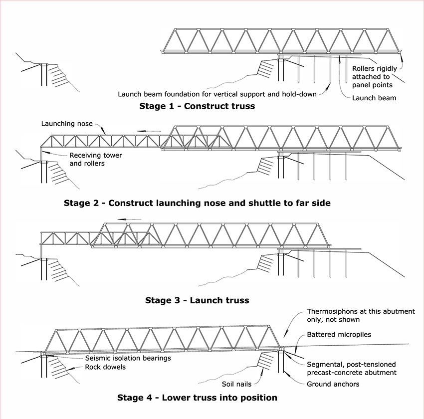
One of the unique aspects of this project was the construction methodology: to first build a balanced cantilever of the permanent truss, then build a launching truss and nose that will shuttle longitudinally over the landslide to the west abutment. Then the launching nose will land on a receiving tower, and the bridge will be lowered to a simple-span final condition state.
Therefore, the bridge was designed for both a cantilever “diving board” condition and a typical simple-span condition between the two abutments. The erection engineering methodology and loading controlled many of the permanent members and connections over the final design condition. This also means that there will be stress-reversal scenarios for many members and connections during and after launch. The bridge’s launch has not yet begun, and many truss members need to resist significant tension and compression over the course of bridge erection.
Ongoing construction
Progress to date has been mostly in the ground, including more than 2.75 mi of drilled and grouted steel. Good progress has been made on the construction of the temporary and permanent works. The major rock cut has been completed, as well as the abutment area stabilization installations of rock dowels, soil nails, and thermosiphons. The foundations and abutments were completed, including the installation and testing of ground anchors and micropiles, as well as the placement and post-tensioning of both abutment footings.
Temporary truss erection supports were installed, and four of the 10 truss bays have been erected. Just before the ability to cross the landslide (even by foot) was lost due to its rapid movement, the project team installed shape accel arrays and thermistor instrumentation to measure the ground temperature profiles and possible ground deformation near the abutments. These instruments are monitored throughout the winter, and they will continue to be monitored as temperatures warm this summer, the bridge loads are applied, and the thermosiphons charged.
The 2025 season is planned to be the final full season of construction, with retaining wall and ancillary bridge and roadway work planned for 2026 and road opening by the summer of 2027. Given the uniqueness of this work, it will be fascinating to see how temperature, ice, permafrost, and landslide movement continue to react to the design described here and how the public will enjoy the new experience on their way to see the mountain.
Gary Conner, P.E., S.E., and Devin Altman, P.E., M.ASCE, are senior bridge engineers for Jacobs in Corvallis, Oregon. Scott Anderson, Ph.D., P.E., M.ASCE, and Brian Collins, P.E., are principal geotechnical engineers at BGC Engineering in Golden, Colorado.
More information about Denali National Park & Preserve, additional project details, a construction blog, and descriptions of the Pretty Rocks landslide with a time-lapse video can be found at nps.gov/dena/learn/nature/pretty-rocks.htm
Project credits
Owner
National Park Service
Contracting agency
Federal Highway Administration Western Federal Lands Highway Division
Structural engineer
Jacobs, Corvallis, Oregon
Geotechnical engineer
BGC Engineering, Golden, Colorado
Construction manager/general contractor
Granite Construction, Watsonville, California
Steel erection subcontractor
KWH Constructors Inc., Issaquah, Washington
Construction engineer
Somerset Construction Engineering, Burnaby, British Columbia
This article first appeared in the March/April 2025 issue of Civil Engineering as “Bridging the Gap.”


