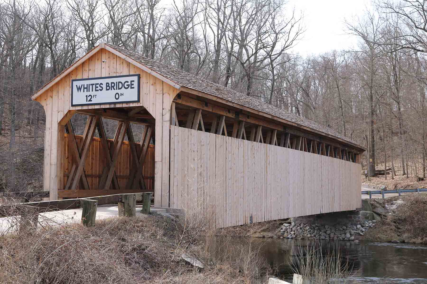
Nearly a decade ago, a 144-year-old covered bridge in Michigan was destroyed by arson. Its recently completed replacement was designed to look as identical as possible to the original structure while meeting more stringent loading demands associated with today’s heavier vehicles.
Nestled at the base of a wooded hill in Keene Township, Ionia County, Michigan, Whites Bridge stood for 144 years until it was destroyed by arson in 2013. Built in 1869 at a cost of $1,700, the span carried Whites Bridge Road across the Flat River. In August 2015, the Whites Bridge Historical Society and the Ionia County Road Commission hired AECOM to design a replica superstructure to be placed atop the remaining abutments. Completed and opened to traffic in June 2020, the new bridge retains as much of the original appearance and structural system as possible while meeting current loading demands.
The structure destroyed in 2013 was the third bridge at the site. The first, a corduroy bridge made of logs, was built in the 1840s by Levi T. White, for whom the bridge and road were named. A second structure of unknown type, built in 1856, was destroyed by an ice jam.
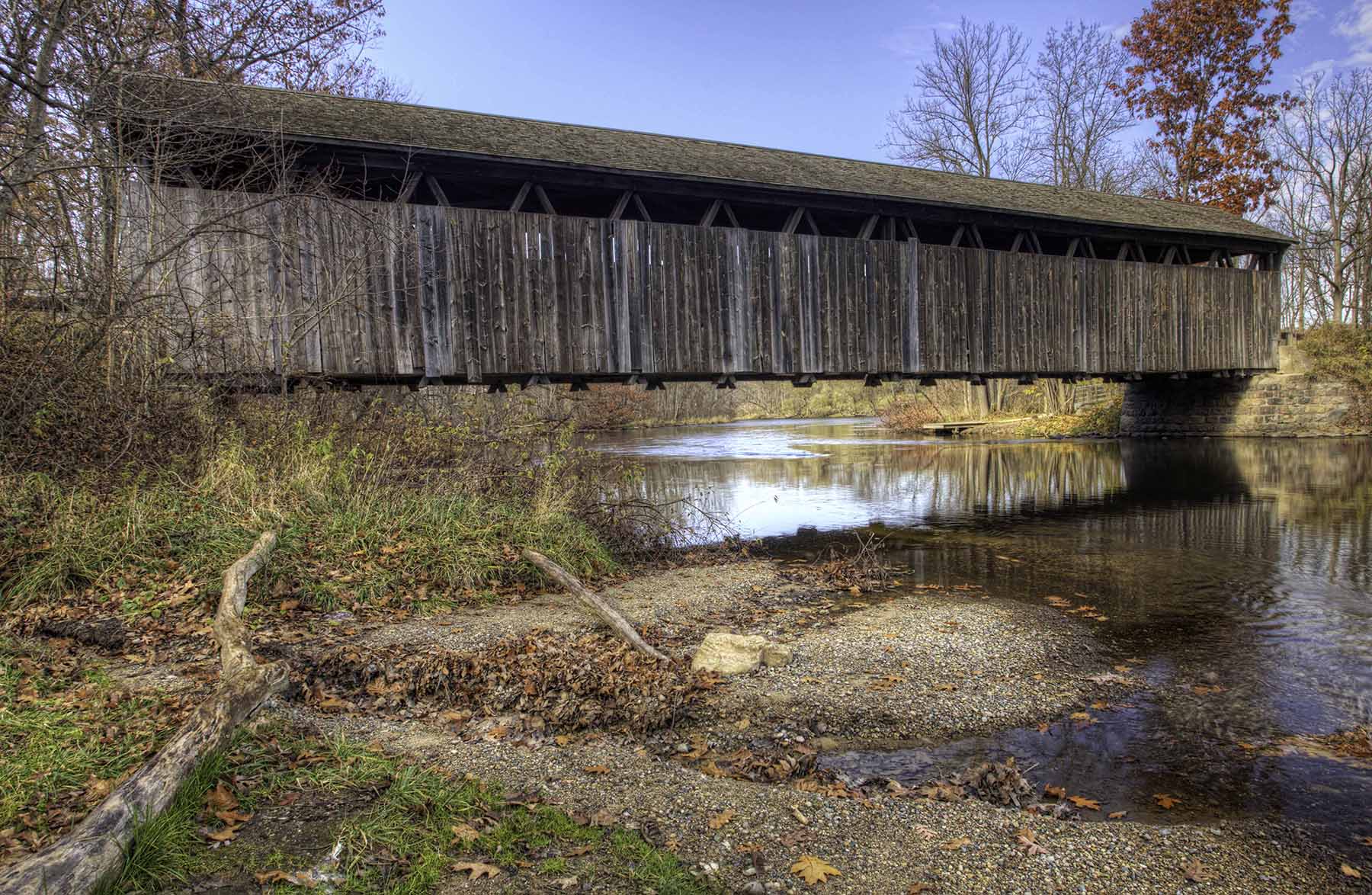
Built by J.N. Walker and Jared N. Brazee, the 1869 covered bridge structure was a 118 ft, 10 in. long single span with a gable roof and wood siding. It sat on cut stone masonry abutments, both of which sustained only minor damage from the fire. The southern abutment is slightly higher than the north, providing a longitudinal slope of 0.79% along the superstructure. A single, 14 ft, 4 in. wide bidirectional lane crossed the bridge; stop signs at each end regulated traffic. The bridge had a 12 ft vertical clearance over a width of 11 ft and a vertical clearance of 10 ft, 9.5 in. at the bottom of the chamfers at the bridge entry opening.
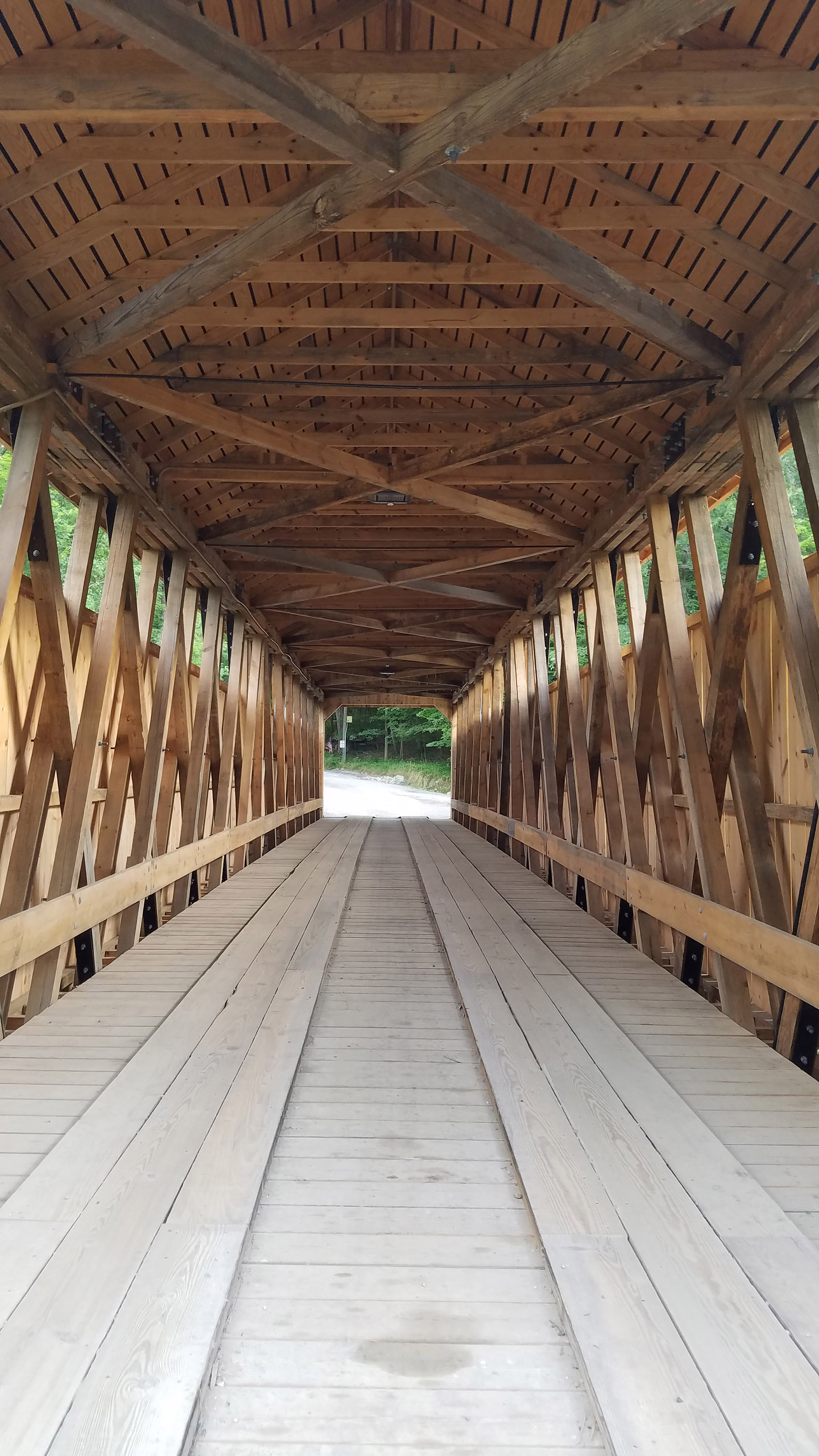
The original structural system consisted of a vertical truss along each side of the travel way with top and bottom sway cross bracing. The trusses were a type patented by Josiah Brown Jr., of Buffalo, New York. Brown’s patent dates to 1857 and included sawn, not hewn, timber, with iron bolts and rods. Each truss was made of a top and bottom chord, crossing X web members, and vertical web members only at the truss ends and midpoint. The top and bottom chords were each made from four plies of an unknown wood species.
The top chord plies were 4 in. by 10 in. and the bottom plies were 4 in. by 12 in. It is assumed the bottom chord plies were spliced at alternating locations with boards that fit into ply notches on each side of a splice point, commonly referred to as a fish splice. This would have created a continuous chord member, similar to other existing Brown-style covered bridges in the area. The top chord plies were spliced with end-to-end, contact-type splices with side wood members between the plies at the splice. The web elements consisted of 6 in. by 8 in. tension members split by 6 in. by 6 in. compression members.
Two other covered bridges in the area have similar Brown truss systems. The Fallasburg and Ada covered bridges are within 11 mi (as the crow flies) of the Whites Bridge site and feature similar truss configurations. Constructed around the same time as the Whites Bridge, the 100 ft long Fallasburg structure was built in 1871 and the 125 ft long Ada span in 1867. The Fallasburg structure was made with Douglas fir. Although it is not known what type of wood was used to make Whites Bridge, it is assumed to have been made from Douglas fir.
The original floor system was made of transverse floor beams and longitudinal stringers supporting transverse floor planks and two sets of longitudinal runners. The floor beams were spaced at 2 ft, 4 in. intervals and were 4 in. by 10 in. in section. The original structure’s approaches contained bituminous wedging ramps adjacent to the bridge’s floor runner locations. The wedging was damaged during the fire, with very little remaining. The original gable roof included trusses, sheathing boards, and, originally, a metal roof, which was replaced with a cedar shingle roof in 1991.
The bridge had been posted for a maximum vehicle live load of 3 tons. The clients requested an increase in live-load capacity for the new structure because a three-axle, 27-ton county maintenance vehicle needed to use it. This vehicle, which has an 18-kip front axle followed by a second and third 18-kip axle spaced respectively at 13.75 ft and 4.25 ft, was used for the design. The design team also reviewed Standard Specifications for Highway Bridges, 17th Edition, from the American Association of State Highway and Transportation Officials, and determined that the live load consisting of a two-axle, 15-ton vehicle or distributed lane loading would not control the design.
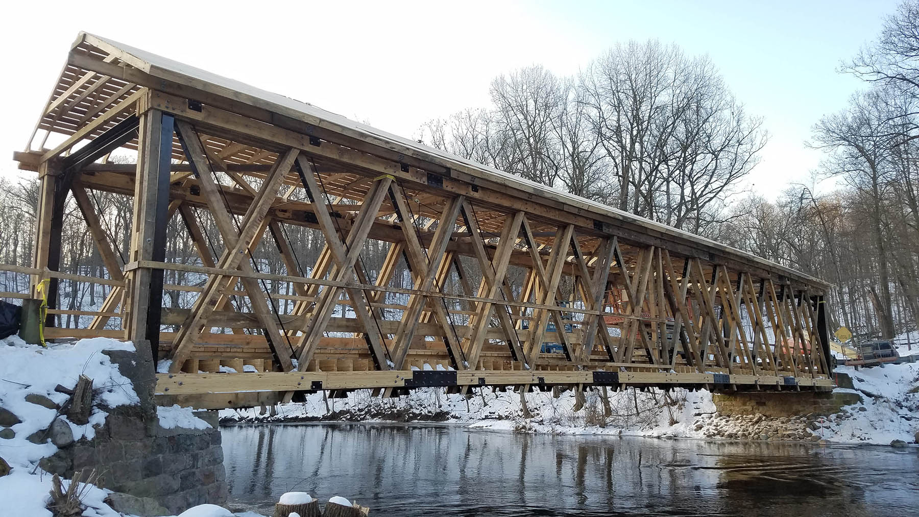
Based in Kalamazoo, Michigan, Building Restoration Inc. inspected and rehabilitated the abutments, including repointing them and replacing damaged or missing stones. Completed in summer 2018, this work was conducted under a separate contract, before construction of the new superstructure.
Gathering guidance
Published by the U.S. Federal Highway Administration in 2005, the Covered Bridge Manual (FHWA-HRT-04-098) can be used to provide guidance for the rehabilitation, construction, and design of wooden covered bridges. This manual was used for general guidance during design of the new Whites Bridge.
Covered bridges vary from typical bridges primarily in that they have walls and roofs that are typically gabled, making them susceptible to snow and wind loads in addition to standard dead and live loads. The wind loading described by AASHTO standard specification documents is for standard structures and thus is not calibrated for a covered bridge. Because of these unique loadings, the Covered Bridge Manual discusses using ASCE 7, Minimum Design Loads for Buildings and Other Structures.
Snow and wind loads can be significant, and the engineers determined that because ASCE 7 contains load combinations with wind and snow, this document would be appropriate for the project’s design load combinations. While conducting allowable stress design, the design team followed AASHTO’s Standard Specifications for Highway Bridges and the American Wood Council’s National Design Specification for Wood Construction.
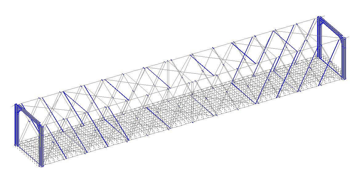
The team determined the load demand for the structure’s main members by using Structural Analysis and Design Software Pro V8i, a general analysis software from Bentley Systems Inc. Because of the relatively complex roof-floor-truss system, accurate load paths from wind, snow, and live load were not easily found. A 3D model of the structure was created in STAAD, Bentley’s 3D structural analysis and design software, to determine the system response. This response involved each truss, sway bracing, and the floor beam and stringer system.
Although the roof trusses were not included, load distribution from the roof was determined for dead load, snow, snow drifting, and wind loads and applied to the top chord of each truss. Therefore, any secondary bracing effects from the roof were not included in the model.
When the wind blows
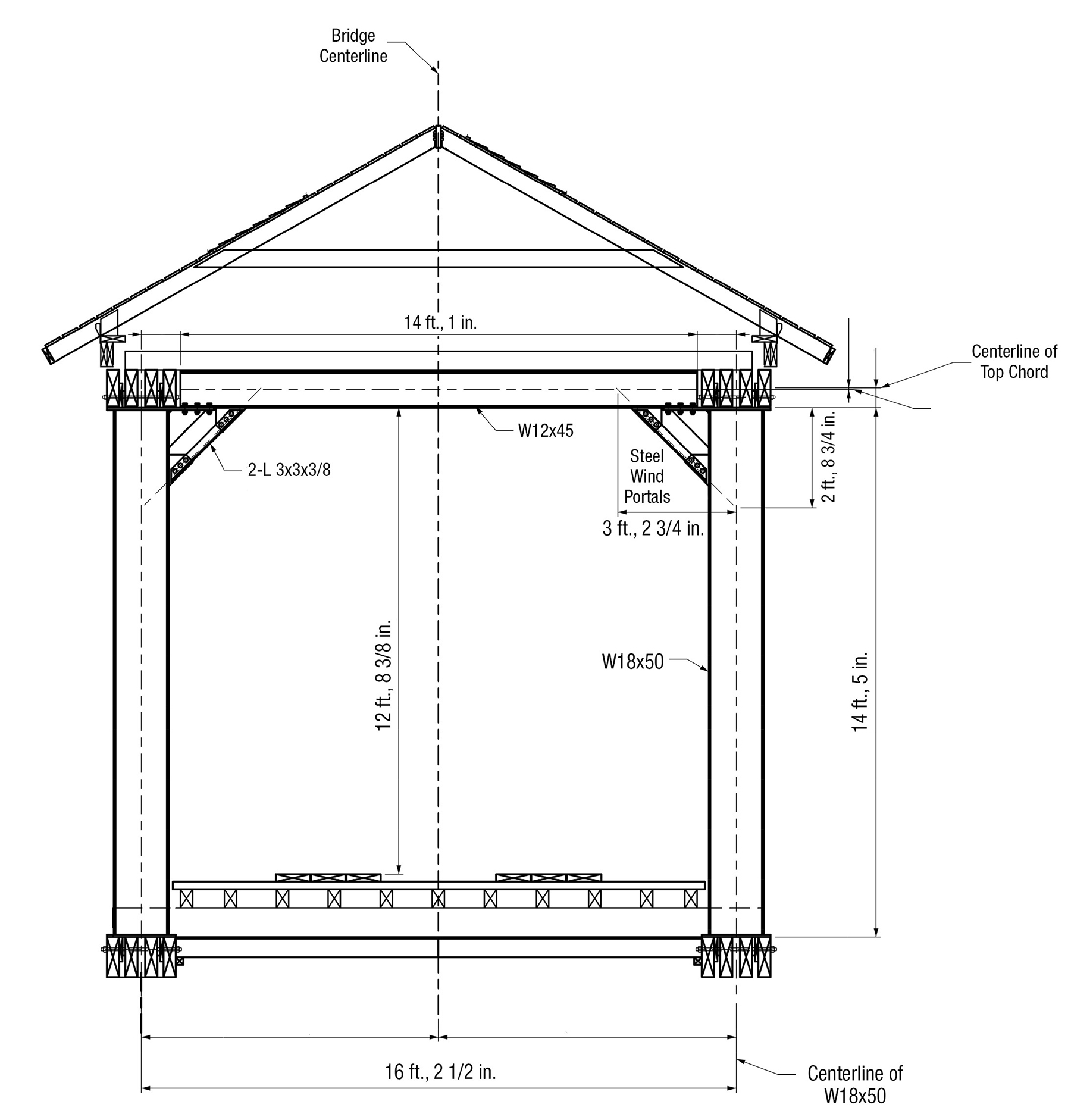
At each end, the new bridge has a 14 ft, 4 in. wide threshold opening that is 12 ft, 3 in. tall at its maximum height and 10 ft, 9.5 in. at its minimum. These dimensions match the width and slightly exceed the opening height of the original structure. The upper-corner chamfers are similar in appearance to those of the original structure.
To help stiffen the bridge for lateral loads, the structural system includes steel wind portals that are connected to the top and bottom truss chords at each end of the bridge. Covered bridges experience significant lateral loads, typically without dedicated lateral stiffening elements. The top and bottom sway bracing cause the two trusses to act as a single unit.
However, if the tops of both trusses translate because of wind loading, sway bracing does not impede translations. This is similar to a simple frame having beam-to-column shear connections but no moment connections, resulting in a frame that is unstable for lateral loading. Even though many load paths from the floor and roof systems may contribute to lateral stiffness, preliminary modeling determined that additional means of stiffening the structure for lateral loads would be required.
As stated previously, roof loading on the truss top chords was applied to the model, but bracing effects were not included, nor were such effects assumed to contribute to lateral wind resistance. The wind portals were included in the STAAD model; their member loading was determined through analysis. The portals are hidden from view, whether inside or outside the structure, behind the end facade. The portal members were created in compliance with AASHTO’s Standard Specification for Structural Steel for Bridges (M270) and comprise 36 ksi steel that has been galvanized and coated black for extended life and concealment.
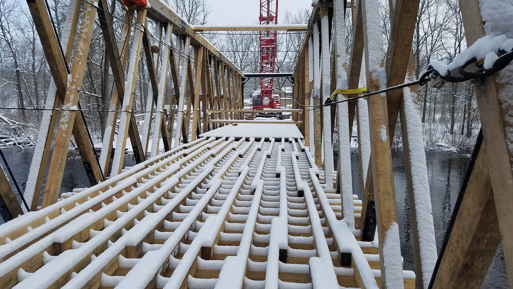
The floor system is similar to the original and had to fit the abutment seat height, matching into the existing approaches. Matching the historic floor configuration was important, even though most of it cannot be seen from within the structure. The floor system includes 3⅛ in. by 9⅝ in. glue-laminated transverse floor beams spanning between the truss bottom chords at intervals of 1 ft, 4 in. Glulam, an engineered wood product, was required to meet the loading demand. Longitudinal stringers measuring 4 in. by 6 in. span between the transverse floor beams at intervals of 1 ft, 4.5 in. Along the structure’s length, the stringers are topped with 3 in. by 10 in. transverse floor planks, atop of which 3 in. by 12 in. floor runners form the wheel path.
The truss system had to replicate the original Brown truss structure while providing increased capacity to meet new loading requirements. This meant that the layout had to be similar, with improvements to members and connections where required.
The overall truss height increased by 1 ft over the original, from 14.5 ft to 15.5 ft. Similar to the original, the top and bottom chords each consist of four plies. However, the bottom chord plies are larger — 4 in. by 13 in. compared with 4 in. by 12 in. in the original. The bottom chord plies are also glue laminated. At 4 in. by 12 in., the top chord plies are also slightly larger than the original, 4 in. by 10 in. chord plies.
Steel sisters
The single web members match the original size. However, to meet demands, 1.25 in. diameter steel rods run adjacent and parallel to the tension members for eight members of each truss. Known as sister members, this concept was successfully used to strengthen the Brown trusses on the Ada and Fallasburg bridges. Like the portals, the rods are AASHTO M270 grade 36 ksi steel that are galvanized and coated black for a somewhat masked appearance.
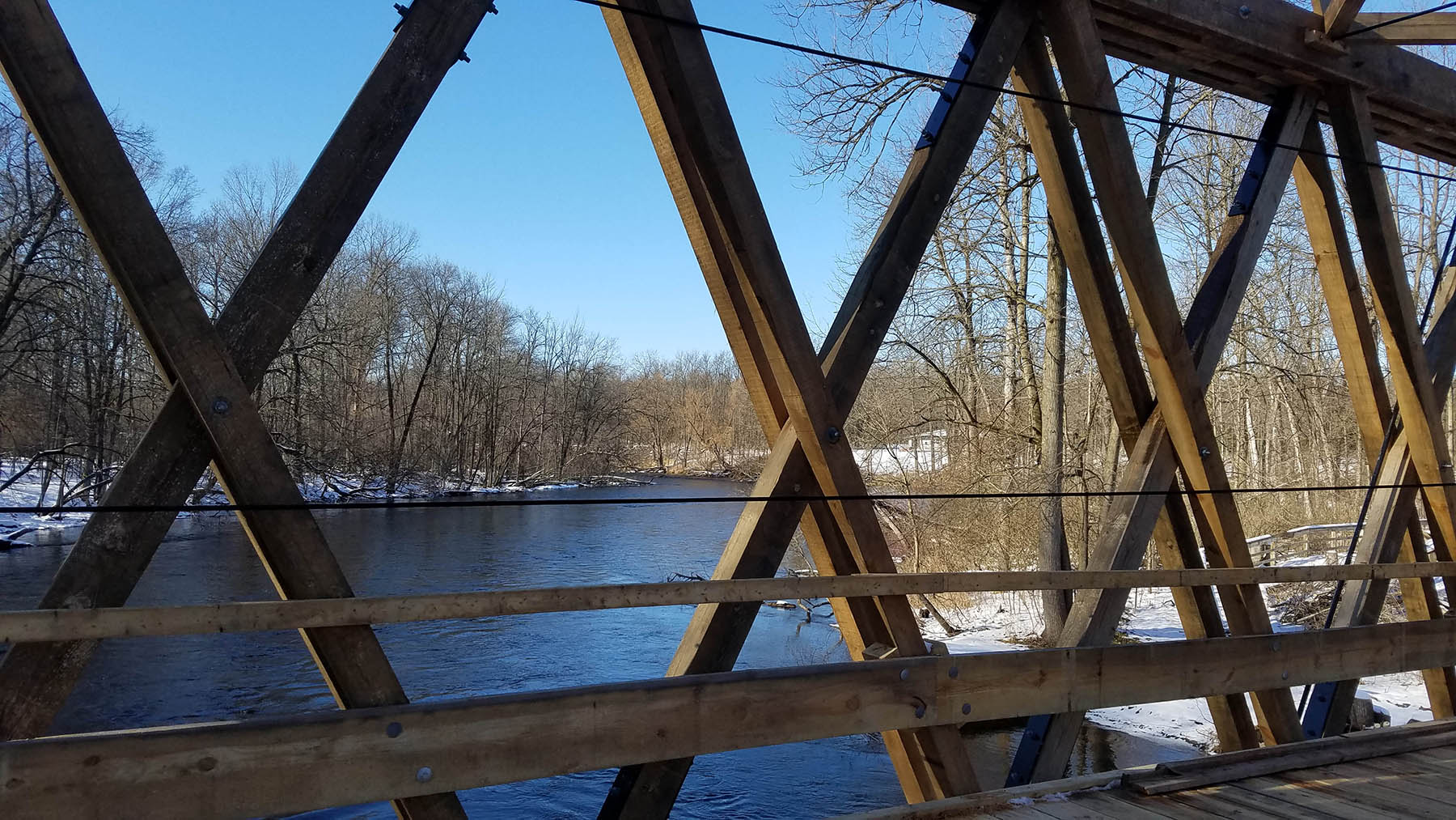
Extending through the top and bottom chords, the rods are attached using a combination of 0.75 in. diameter bolts with shear plates and plates bearing against the chords. To provide additional capacity, the connections for the single web tension members vary from the original, with steel sleeve ends that bear against the top and bottom chords. The sleeves are galvanized, coated black, and open at the end, allowing improved ventilation for moisture resistance. Connections and splices throughout the structure use shear plates and malleable washers at several locations.
The roof system replicates the original with improvements to meet current loading demands. The original roof plans were limited, lacking member sizes and connection details. Historic photographs of the inside of the structure were also limited; none showed such details as the sill plate or the connection of the roof truss to the sill plate.
The new structure has a wooden cedar shake roof, matching the original style. But plans called for two modern, electrified additions: lighting and security cameras. These are meant to help prevent vandalism or arson incidents.
Building it back
The anticipated construction sequence included two possible methods. The first would require constructing the main trusses with transverse floor beams and sway bracing on the northern shore, followed by lifting the entire assembly into position over the river and completing the superstructure roof and siding in place. The second method involved assembling each truss onshore, lifting each onto the abutments, and then completing the structure in place over the river.
The second method required a temporary support system in the river and a permit for placing the supports in the river. The Michigan Department of Environmental Quality — now known as the Michigan Department of Environment, Great Lakes, and Energy — granted a permit that would allow for temporary supports in the river but excluded the time period of Oct. 1-April 30 to mitigate any disruption to spawning and/or migrating fish.
The contractor, Davis Construct-ion Inc., chose the second method, using temporary steel-pile supports in the river. The construction sequence included fabricating each truss on the approach, in the flat position, then placing each truss on the abutment bearings using a crane. To brace each truss during this sequence, steel H-piles were driven in the river ahead of truss placement. A total of four piles were used for the bridge, with the trusses secured to the piles using chains or cables. The wind frames, transverse sway bracing, and transverse floor beams were then erected, and the piles were then removed.
Once the piles had been removed, the remaining floor system and roof were installed. The roof was partially constructed on the northern shore and lifted onto the superstructure in sections. The siding was placed on all four exterior walls, and then the roof shingles were placed as the last fabrication step. Final construction tasks included installing new approach asphalt for the northern roadway, which had been damaged by crane tracks, and the guardrail.
Completed at a cost of approximately $690,000, the structure was put into service as soon as the power, lighting, and security cameras were installed. Funding for the project came from various sources, including grants from Michigan’s Local Bridge Program and the Michigan Economic Development Corp., private donations, Keene Township, a group known as Rebuild Whites Bridge, and the Whites Bridge Historical Society. The structure has performed well thus far in 2021, and a proper opening ceremony has been proposed for after the COVID-19 crisis has subsided.
Greg Garrett, P.E., M.ASCE, is a senior bridge engineer at AECOM, working in the Grand Rapids, Michigan, office.
PROJECT CREDITS
Owners: Whites Bridge Historical Society, Lowell, Michigan; Ionia County Road Commission (now the Road Department for Ionia County)
Superstructure design: AECOM, Grand Rapids, Michigan, office
Abutment inspection and rehabilitation: Building Restoration Inc., Kalamazoo, Michigan
Shop drawing production: Cogent Civil Engineering LLC, Alto, Michigan
Superstructure construction: Davis Construction Inc., Lansing, Michigan
Power, lighting, and security system: Strain Electric, Wyoming, Michigan
Signs: United Sign Co., Saranac, Michigan
This article first appeared in the July/August 2021 issue of Civil Engineering as “Replaced with a Replica.”


