
By Ryan Anderson, S.E., DBIA, Sam Bass, P.E., and Shruti Sharma, P.E.
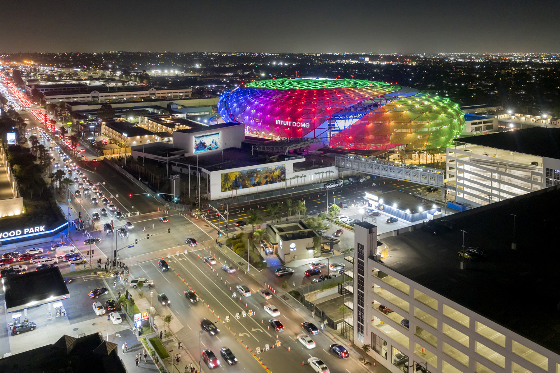
The Intuit Dome in Inglewood, California, is a dream turned reality, a testament to environmental sustainability, and a commitment to unforgettable fan experiences.
Immediately after buying the National Basketball Association’s Los Angeles Clippers in 2014, Steve Ballmer began planning for a new home exclusively for his team. He envisioned creating an iconic venue that would be the most fan-friendly and environmentally responsible arena in the league. His dream did not stop there, however. He also wanted to consolidate every facility needed by his team — practice courts; training, medical, and relaxation spaces; and team offices — under one roof. And he wanted his complex to foster com-munity engagement at an unprecedented level.
When Intuit Dome opened in August 2024, it surpassed even Ballmer’s expectations. The 18,000-seat arena — uniquely configured to provide incredible fan experiences and equipped with the largest video halo board in the league — anchors a 1.1 million sq ft multicomponent complex.
Walter P Moore was selected by the architect and owner’s representative to serve as lead structural engineer, perform a whole-building life cycle assessment, and coordinate the environmental product declarations program. The firm was subsequently hired by the contractor to design and detail connections for the ethylene tetrafluoroethylene and polytetrafluoroethylene-covered diagrid shell roof as well as provide erection engineering services for the project.
Architectural design and features
The main arena is separated from the team practice facilities and administration building components by the main entry plaza. To the north of the arena, an 80,000 sq ft plaza that is open to the public year-round includes a concert stage, community basketball courts, and a giant LED screen with space for the public to watch everything from Clippers games to movie premieres.
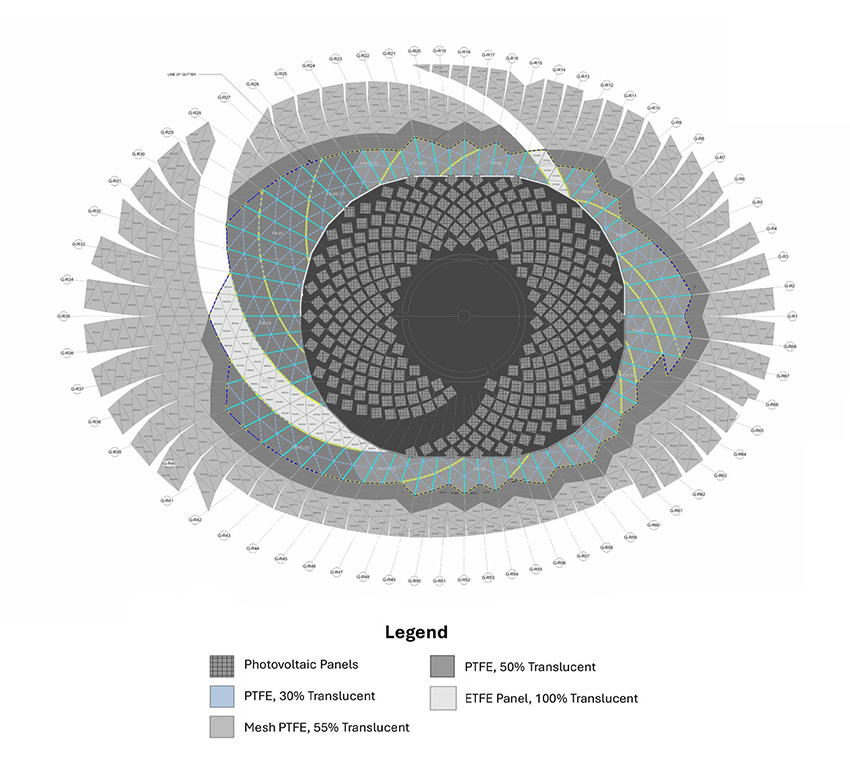
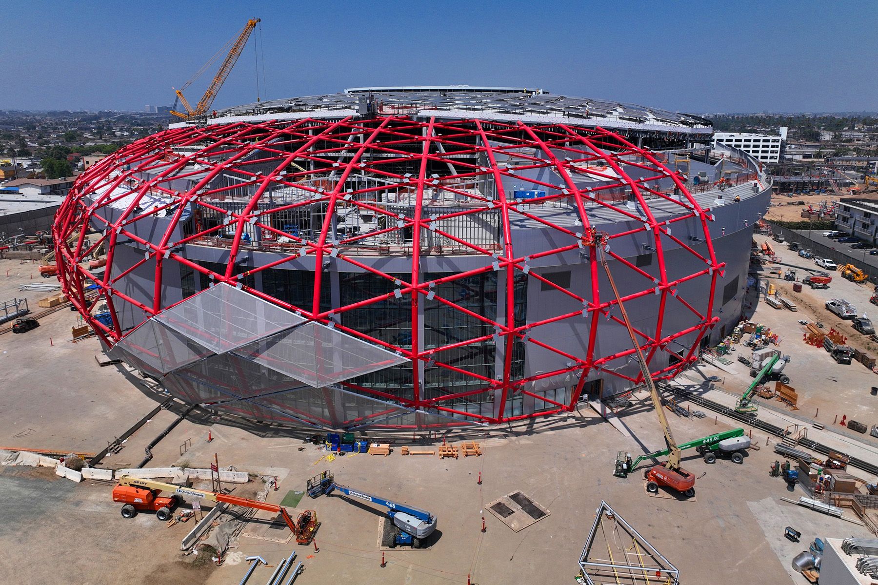
A 277,000 sq ft oval diagrid roof structure — substantially larger than other NBA arenas — covers the entire complex. The 2,800-ton diagrid forms diamond-shaped openings that are roughly 20 ft by 30 ft. The openings are infilled with a combination of translucent PTFE membrane, clear ETFE membrane, and woven mesh PTFE. They provide opacity and weather protection over those spaces that require it and clear views to the sky. They also allow natural airflow over the main plaza, the main entry lobby, and several indoor/outdoor sky gardens within the arena.
The open-matrix membrane roof eliminated the need for air conditioning in any of the indoor/outdoor spaces and the covered plaza.
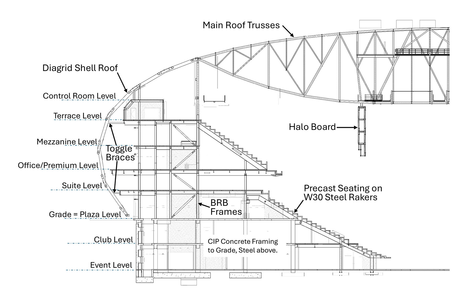
The main arena structure consists of eight levels: two below grade, the main concourse at grade, and five levels above grade. The arena event level is 32 ft below natural grade, forming a bowl. To create an intimate game experience for patrons, the bowl structure is divided into five distinct areas: the lower bowl, the mid bowl, the upper bowl, the “dugout suites” area (so named because they are partially below the court level like a baseball dugout), and the “Wall,” which is on the east side of the bowl. It has 50 rows of uninterrupted seating reserved for the most ardent fans, who raise the loudest cheers. These cheers are funneled down to the court, acting as a wall of energy and excitement.
There are 40 suites arranged in a horseshoe at the back of the mid bowl. These suites also provide dedicated seating within the mid bowl. Ten court-level dugout suites also include access to seats in the lower bowl. Four more dugout suites adjacent to the player tunnel offer patrons closeup views through privacy glass of players coming and going to the court.
The main entry plaza and ticketing lobby make up a 25,000 sq ft indoor/outdoor space covered by the diagrid shell roof 115 ft above.
Intuit Dome’s concourses offer additional fan entertainment and engagement opportunities. The west side of the upper concourse includes a 14,000 sq ft indoor/outdoor terrace. In addition to concessions, landscaping, and shade trellises, the terrace level offers fans the Shoot 360 interactive experience, which consists of four basketball hoops with automatic ball returns and an electronic scoring system.
Loading dock and central utility plant
The basement level measures 1,300 ft by 450 ft and includes a 300 ft long loading dock ramp to speed loading and unloading for events. Steel transfer trusses span the loading dock, providing a column-free zone that provides ample maneuvering room for trucks. The trusses support an open plaza above.
A designated area at the plaza level provides modular storage for 180,000 lbs of central utility plant batteries and related equipment that help Intuit Dome achieve energy-neutral status. This area was designed to allow new technologies to be added as they are developed.
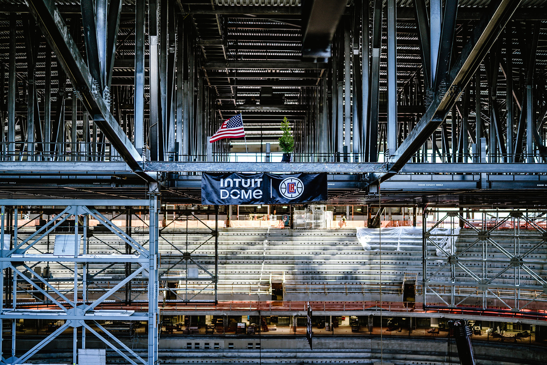
To ensure that Intuit Dome can support the lighting and sound demands of even the largest and most ambitious touring acts, the team suspended from the seven main roof trusses a comprehensive catwalk system and grid of rigging beams to support both center-stage and end-stage shows.
Each rigging beam can support 5,000 lbs vertically or in a bridled configuration. Each truss was designed to individually support up to 75,000 lbs, and the entire grid can support up to 525,000 lbs, much more than even the largest touring shows.
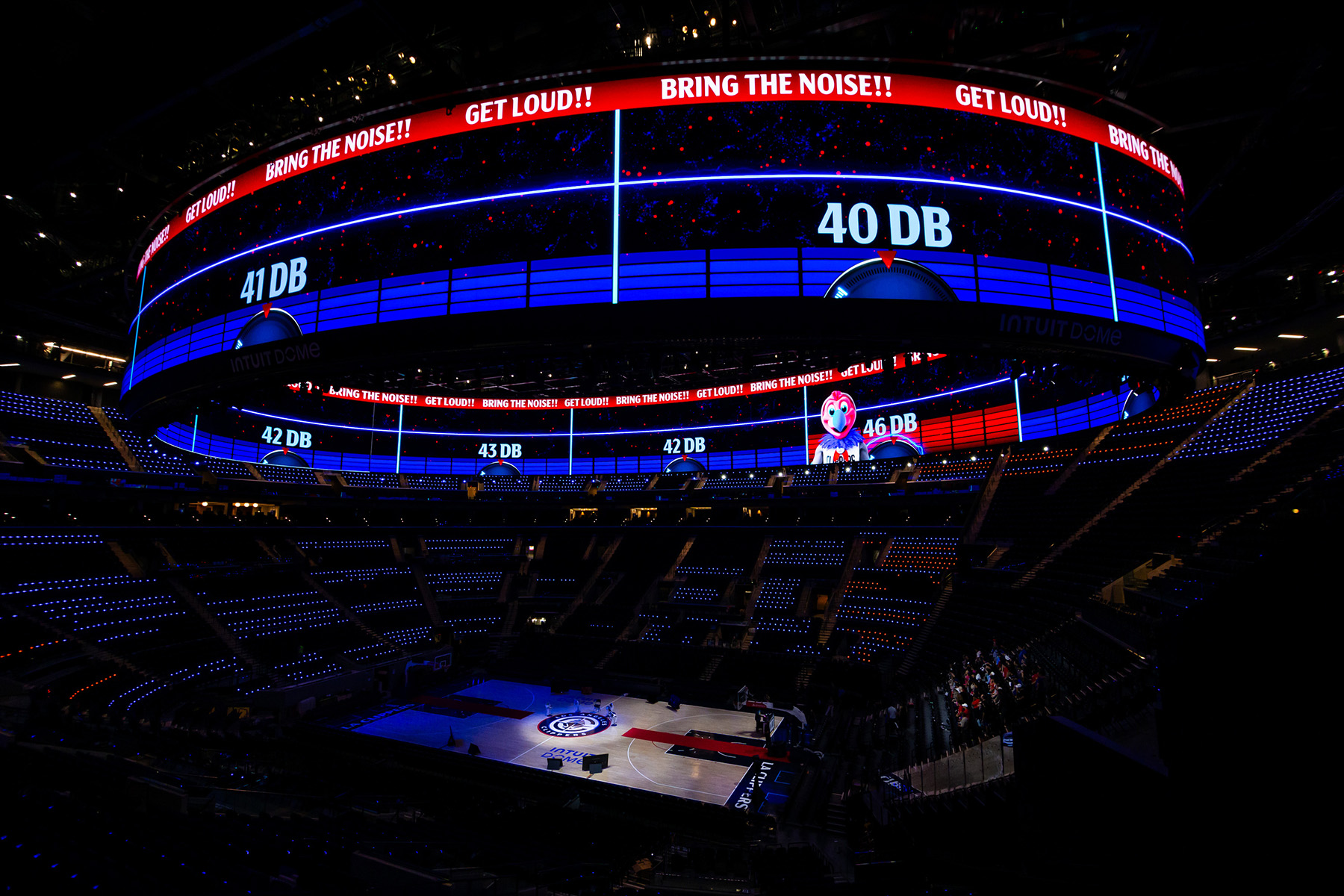
The “star” of the fan bowl experience is undoubtedly the double-sided halo 4K scoreboard that is suspended from the roof trusses over the court. The size and location of the board optimize sightlines from all seats, with priority given to those seated in the upper bowl farthest from the court.
The 30 ft tall video board features more than 233 million LEDs and is the largest-ever double-sided halo display in an arena setting. The halo board includes retractable end sections for special events as well as T-shirt cannons to launch team merchandise to fans at all levels of the venue.
Outside the west side of the bowl, a secluded 30,000 sq ft sunken garden provides private outdoor space for players to relax and socialize. The garden includes a swimming pool, infrared sauna, plunge pool, outdoor track, lounge, and eating area. Terraced, mechanically stabilized earth walls support the steep slope from natural grade down to the 86,000 sq ft indoor practice facility, which allows sunlight to flood the practice courts while also providing privacy for the team.
A 60 ft ceiling above the east side of the main concourse provides ample height for community-use basketball courts. To keep this 12,000 sq ft area column-free, the engineers used a series of 95 ft long by 12 ft deep trusses, sized to limit floor vibrations to support the terrace above.
Finally, a separate four-story building provides 71,000 sq ft of office and meeting spaces for team administrative activities.
Structural design approach
The structural engineer employed a combination of structural typologies to address the demands of the project. The substructure is reinforced cast-in-place concrete. This includes the arena’s foundations, perimeter basement retaining walls, slab-on-grade at the main event level, and elevated 11 in. to 12 in. thick flat slabs with concrete columns at the club and plaza levels.
These levels were designed as two-way slabs and analyzed under gravity loads. To simplify placement of rebar in these areas, flexural reinforcing was detailed uniformly in the top and bottom base layers in each direction; additional reinforcing was specified where flexural demand exceeded the capacity of the base layers.
Headed stud rails provide the punching shear resistance at slab-to-column connections. Concrete beams were added where necessary to provide additional stiffness to the slab at longer spans and around openings for stairs and elevators.
The portion of the plaza level over the loading docks is supported on 14 ft deep by 150 ft long A913 Grade 65 steel trusses with concrete on metal deck flooring. These trusses must support more than 250 psf of landscaping and hardscape overburden plus up to 250 psf of live load for vehicles, equipment, and event staging.
The majority of the arena superstructure — including the suite, mezzanine, and terrace levels — uses composite concrete floor over composite metal deck with composite wide-flange steel beams. The seating bowl consists of L-shaped lightweight precast-concrete seating units spanning between wide-flange steel raker beams with W14 column frames.
Lateral loads due to fan sway and seismic forces are collected and delivered to the floor diaphragms by under-bowl diagonal bracing, with additional buckling-restrained braces at the bottom section of the lower bowl. The rakers are not connected to each floor level to prevent them from structurally behaving like diagonal building braces.
To support the upper concourse above the main entrance plaza, the engineers took an unconventional approach, framing the concourse with a cantilevered floor plate with the seating bowl serving as counterbalance. The entire system was carefully analyzed to limit dynamic vibrations to ensure patron comfort.
The lower bowl on the west side is connected to the plaza, club, and event levels, eliminating the need for objectionable seismic joints at the premium suites. The project team designed the connections at the club level to accommodate seismic drift compatibility forces, which were mitigated by the relatively stiff concrete shear wall system.
The concession areas are steel-framed structures using wide-flange beams and hollow structural steel columns. They use cold-formed, steel shear walls to resist seismic forces. The exterior walls of the concession buildings are curved to follow the facade wall, with an adequate gap designed to allow the diagrid shell to move independently from the superstructure.
Engineers used composite steel framing for the four-story administrative building. A series of 16 ft deep transfer trusses span 145 ft over the practice facility embedded below the building, transferring the forces from the building columns and keeping the practice courts column-free. Sophisticated stage-loading analyses ensured floor levelness within tolerances and mitigated perceived structural vibrations.
The halo video board is framed using vertical and horizontal steel trusses curved in plan to multiple segmented radii, creating the overall 260 ft by 160 ft oval shape of the board. The trusses primarily consist of HSS tubes that are field-connected to create a continuous structure. Retractable truss segments at each end extend the video board to support specialty shows and events. The board is suspended by structural steel hangers from seven main roof trusses above; special clamp connections provided installation adjustability in multiple directions.
In addition to its 1 million lb weight, the mass and stiffness of the halo were incorporated into the structural analysis of the roof truss system to account for load redistribution and stiffening effects.
Walter P Moore’s construction engineering specialists were separately engaged to help the erector and fabricator develop strategies to most efficiently erect the video board. A conventional approach would have called for the video board to be assembled on the event floor, then lifted into place by cranes. But the size of the required lifting equipment made this approach infeasible, so the team engineered the halo truss superstructure as a series of “picture frames” that were independently assembled on the event floor and then individually raised into place in a careful sequence. Once in place, each picture frame was secured to the adjacent frame with field-bolted connection plates.
Seismic approach
The site is about a mile from the Newport-Inglewood Fault, which could produce a maximum credible earthquake of Richter magnitude 7.4. As a result, every structural component and system was designed to resist substantial seismic forces.
The seismic base, consisting of a continuous perimeter retaining wall and interior shear walls, is founded 32 ft below the arena’s natural grade. The basement uses a special seismic frame concrete shear wall that combines the perimeter retaining walls and interior shear walls of 12 in. to 30 in. thickness.
Reinforcing detailing followed provisions of ACI 318-14 Building Code Requirements for Structural Concrete (American Concrete Institute, 2014). The team used Grade 80 reinforcement throughout the foundations, shear walls, and flat-plate slabs to relieve congestion and reduce embodied carbon.
The diaphragm connecting the base elements is an 11 in. to 12 in. thick CIP reinforced-concrete slab. At the east side of the plaza level over the loading dock, the diaphragm consists of a composite concrete slab atop composite steel deck. The team designed the concrete superstructure using a static linear approach via a modal response spectrum analysis.
Above grade, lateral forces in the steel superstructure are resisted by a buckling-restrained brace lateral system that collects and transfers seismic forces to the seismic base. BRBs are distributed regularly throughout the arena structure at approximately 70 ft to 80 ft spacing.
The BRB system stacks vertically through the arena and uses a single diagonal approach. The lateral systems of the main arena and the administrative office structures were scaled to minimize load sharing through the connecting floor diaphragms.
The W14 column frames were analyzed with continuous columns, as well as fixed or pinned connections at beam ends, depending on the connection details used. The column bases at the BRB frames were analyzed and detailed as pinned in order to drive the forces into the braces.
The four-story administrative building also uses a system of BRBs to provide seismic bracing. However, the column-free practice courts forced the locations of BRBs to be extended to the extreme ends of the building, 140 ft apart, dictating substantial reinforcement of the floor diaphragm with collector beams and the largest BRBs in the complex.
Traditional engineering thinking suggests that buildings of disparate size, height, and configuration in high-seismic zones must be separated with large seismic joints to allow the various elements to move independently during a significant seismic event. But most seismic joints are disruptive to function and aesthetics and expensive to maintain.
So the engineers combined the BRB lateral frames with sophisticated thermal and shrinkage analyses. This alternative approach required more complex structural analyses, but it paid off with superior functionality and lower construction and maintenance costs.
The roof and diagrid shell
Seven conventional 46 ft deep steel trusses span 360 ft over the main arena to support the rigging, catwalks, halo board, and 2 MW of roof-mounted photovoltaic solar panels that provide power for the entire complex. An oval, steel, perimeter gutter consisting of two orthogonal wide-flange beams surrounds the roof to create a supporting edge for the diagrid shell roof.
Engineers performed dozens of design iterations using hundreds of load combinations to fully consider and optimize the integrated structural performance of the video board frame, roof trusses, catwalks, lighting platforms, and rigging grid under extreme seismic loadings during different possible event configurations.
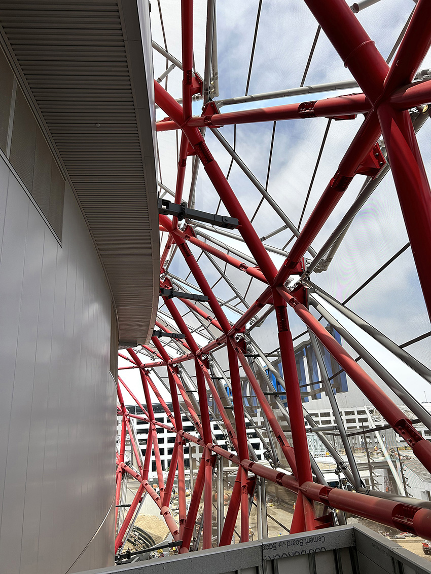
The structural design of the diagrid shell was key to the entire project. The shell structure uses circular 12 in. to 24 in. diameter HSS members — formed from a series of diamond-shaped panels that reflect the geometry of a basketball net — to work as a three-dimensional grid structure that supports the PTFE and ETFE membranes that enclose the complex. The diagrid shell is vertically supported at the suite and terrace levels by traditional columns and tree columns with horizontal outriggers.
A 12 in. vertical gap at the bottom of the shell, where it ends just above the plaza level, ensures that the shell is not base-supported or seismically restrained at grade at any location. The shell is braced laterally at the gutter interface between the arena’s truss roof ring as well as with radial braces at the terrace and suite levels.
The entire shell was analyzed as a continuous 3D diaphragm and uses overstrength loading design forces. It uses its geometry and grid behavior to span and cantilever as much as 100 ft between gravity supports.
The shell does not meet a prescriptive seismic code-based approach, but a formal performance-based design would have exceeded the design and permitting time available. As a result, the structural engineer adopted a different approach to ensure the shell complies with all existing structural and seismic codes.
The seismic response of the light diagrid shell would be substantially different than that of the main arena structure, so connecting them rigorously together would induce substantial unwanted forces to the roof and the shell. So the diagrid shell is connected to the roof level of the arena and administrative building in a way that allows it to “ride along” with those roof structures as they move during a seismic event. The lateral stiffness of the administrative building was tuned to prevent significant force transfer through the diagrid shell.
The key was to keep the sides of the shell from collapsing inward or splaying outward. To accomplish this, the project team created an innovative toggle-brace connection that allows the shell to seismically sway around the facility while still providing needed axial support for the diagrid. The rest of the diagrid is allowed to independently and seismically respond without vertical constraint. In effect, the diagrid shell is laterally connected only at the arena roof and is allowed to gently swish like a hula skirt around the more rigid brace frame structure below.
Each toggle-brace is a rigid strut capped at either end by two perpendicular pinned connections. These connections can rotate freely in all directions, but the rigid strut keeps the diagrid within a thin movement envelope around the building.
A carbon-neutral venue
The owner challenged the project team to reduce embodied and operational carbon emissions throughout the project. The roof-mounted photovoltaic solar panels energize 11 MW of batteries in a central utility plant, storing enough clean energy to power an entire basketball game or concert.
The whole-building life cycle assessment highlighted the relative contributions of embodied carbon from each construction material in the project. As usual, concrete was the most significant contributor, so the structural team focused on global warming potential as a performance measure, quantified through environmental product declarations.
Intuit Dome was one of the first projects in California to require supply chain-specific environmental product declarations for all concrete mixes used on the project. The declarations developed by the ready-mix supplier showed that by using a combination of high-quality aggregate, supplementary cementitious materials, and Type 1L blended cement, the embodied carbon of the concrete was reduced by more than 20% compared to typical concrete mixes used in the region.
California included new embodied carbon requirements for concrete in the update to the California Green Building Standards Code, also known as CALGreen, that took effect in July. While these requirements were neither applicable nor fully developed at the time of the project design three years ago, Intuit Dome’s concrete mixes are 50% better than the new CALGreen embodied carbon thresholds, demonstrating the project’s leadership in reducing embodied carbon.
Into the future
The signature diagrid shell roof has already made its mark on the LA landscape and firmly establishes a sophisticated identity for the Clippers. Inglewood and the surrounding communities have embraced the Clippers and have started using the campus plaza to host community events. The project remains on target to achieve LEED Platinum certification — the first NBA arena to do so under LEED v4 — and, as a carbon-neutral facility, it has set a new benchmark for sustainability among major sports venues.
The Clippers inaugurated their new home court with a pre-season game against the Dallas Mavericks on October 14. Intuit Dome has also been tapped to host the 2026 NBA All-Star Game and will serve as the host venue for basketball and gymnastics for the 2028 Olympics.
Ryan Anderson, S.E., DBIA, is a principal of Walter P Moore and served as the firm’s structural engineer of record for the project. He founded and leads the firm’s San Diego office. Sam Bass, P.E., is a principal of Walter P Moore and served as the firm’s structural project manager for the project. He works in the firm’s Los Angeles office. Shruti Sharma, P.E., is a principal of Walter P Moore and served as sports venue design specialist. She works in the firm’s Houston office.
Project credits
Owner
Los Angeles Clippers, Inglewood, California
Owner’s representative
CAA ICON, Denver
Architect
AECOM, Los Angeles
Structural engineer
Walter P Moore, Los Angeles
Associate structural engineer
Labib Funk + Associates, El Segundo, California
Contractor
AECOM-Hunt–Turner joint venture, Inglewood
Civil engineer
D and D Engineering Inc., Inglewood
HVAC engineer
AECOM and Henderson Engineers, Los Angeles
Steel fabricator/erector
Schuff Steel, Phoenix
Concrete subcontractor
Largo Concrete, Los Angeles
Ready-mix concrete supplier
Catalina Pacific, Orange County, California
(now a subsidiary of CalPortland)
Landscape architect
Hood Design Studio, Oakland, California
This article first appeared in the January/February 2025 issue of Civil Engineering as “Lean and Green.”


