By Michael Zimmermann, Dipl. Ing, and Andreas Pfadler, Dipl. Ing
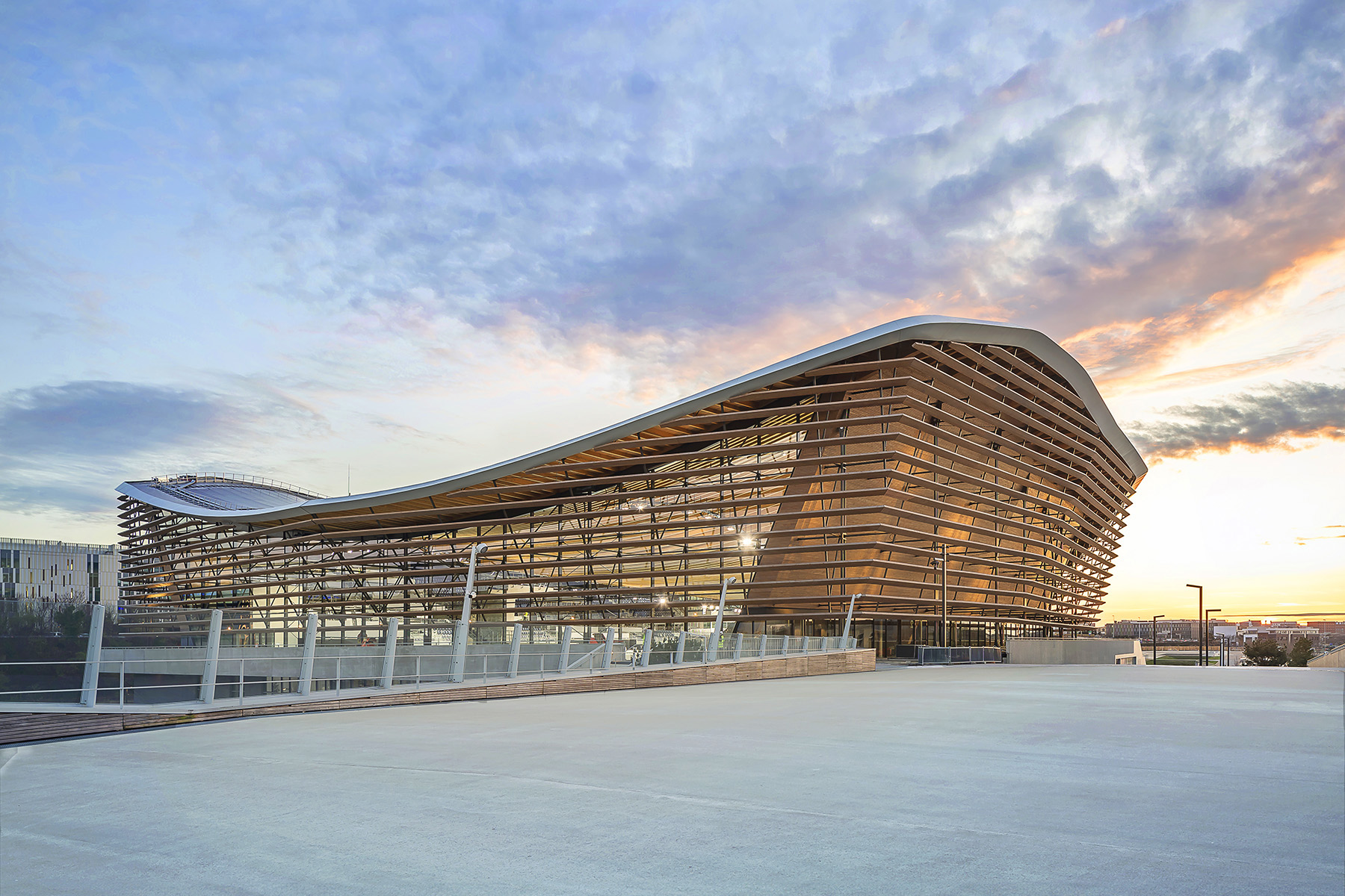
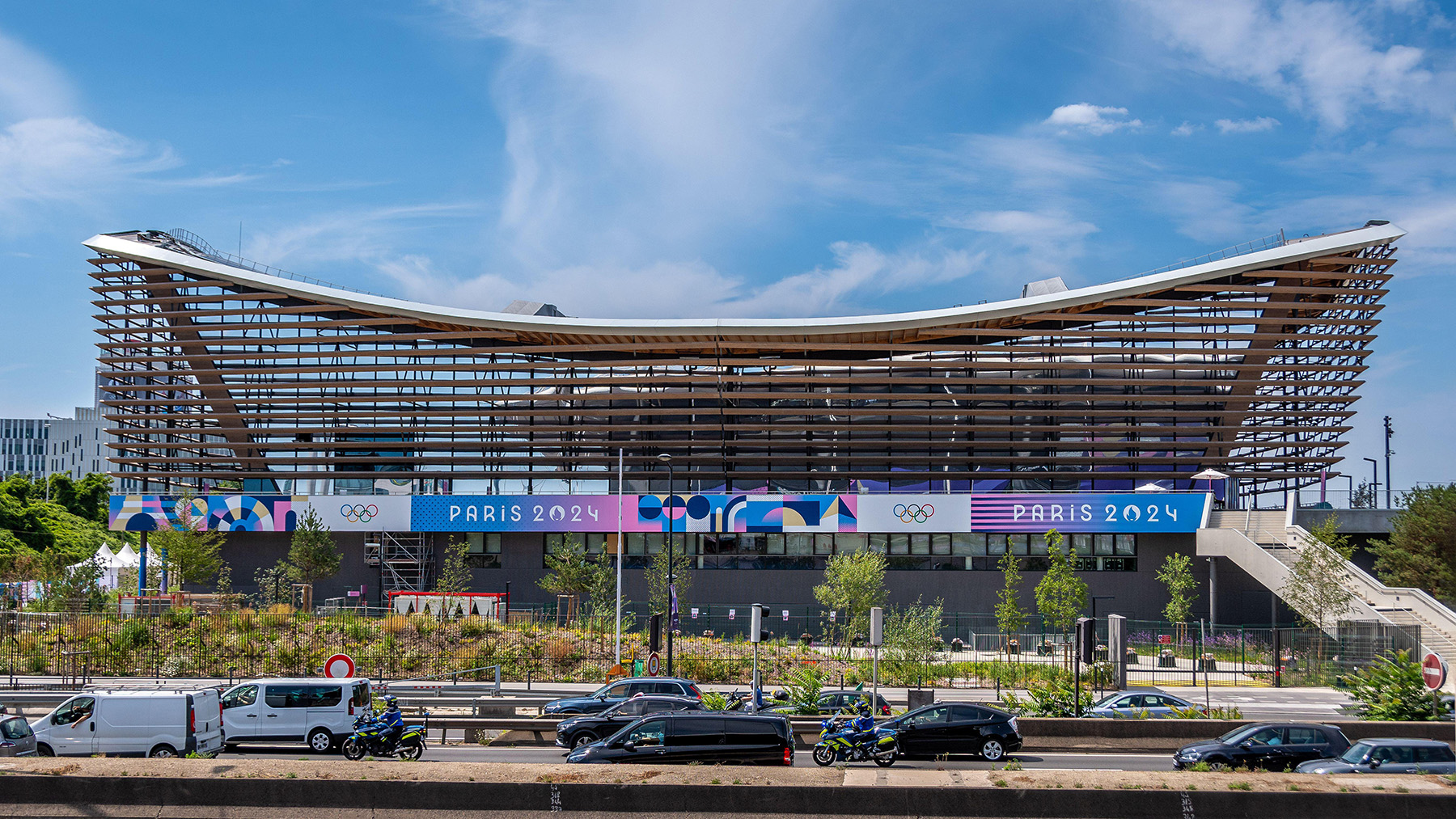
The Centre Aquatique Olympique in Saint-Denis, Paris, was one of a few new facilities designed and built for the 2024 Summer Olympics. Its legacy will live beyond the Games, offering much-needed recreational opportunities for the surrounding neighborhoods.
Since 2020, the International Olympic Committee has expressed interest in holding Olympic Games that not only consider athlete and host city needs but also account for short- and long-term sustainability outcomes. Through Olympic Agenda 2020+5, the IOC set guidelines, aided by the United Nations’ sustainable development goals, that ensure host cities prepare for and follow through on development parameters that respect the local environment.
The 2020 Tokyo Summer Olympics and the 2022 Beijing Winter Olympics featured a few sustainable projects. However, sustainability took center stage in preparation for the 2024 Paris Olympics. To decrease the Games’ carbon footprint by 50% compared to the previous Summer Games in London and Rio de Janeiro, the city built very few entirely new venues. Among these is the Centre Aquatique Olympique, which was built in the suburb of Saint-Denis.
During the Games, the Centre hosted the high-diving, synchronized swimming, and water polo competitions. Its design supports the needs of athletes and spectators while also meeting ambitious IOC sustainability targets, especially through its timber catenary roof and the facility’s adaptive reuse potential.
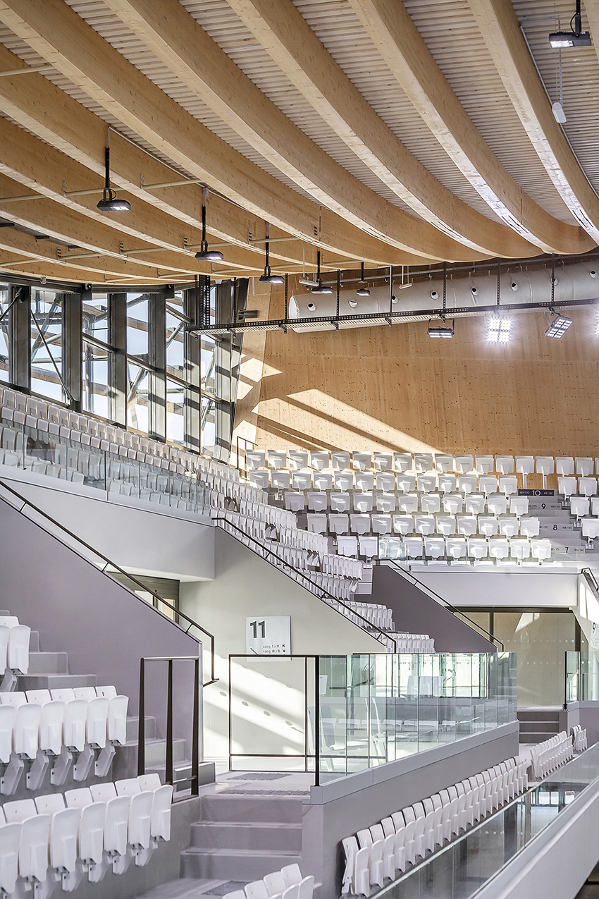
For example, half the 6,000 grandstand seats installed temporarily for the Olympics will be reinstalled for the 2026 European Aquatics Championships. The Centre will also serve as a national base for the French high-diving team.
The design team was chosen through a design–build competition that took place in March 2020 that was hosted by La Métropole du Grand Paris. The winning team included the architecture firms VenhoevenCS and Ateliers 2/3/4/, as well as the structural engineering firm schlaich bergermann partner. Bouygues Bâtiment Ile-de-France was the main contractor; Mathis SAS was commissioned to build the timber structure.
The Centre Aquatique Olympique is part of the future La Plaine Saulnier development project, which includes the creation of a new residential area around the swimming center. The project will help redevelop the former industrial site.
Plan overview
The Centre can be structurally divided into two independent elements: the substructure and the superstructure.
The substructure is a two-story concrete base that sits on the ground without additional excavation. Founded on piles extending up to 68 ft deep into the Paris Basin, the substructure houses technical facilities for water treatment, training rooms, and additional swimming pools.
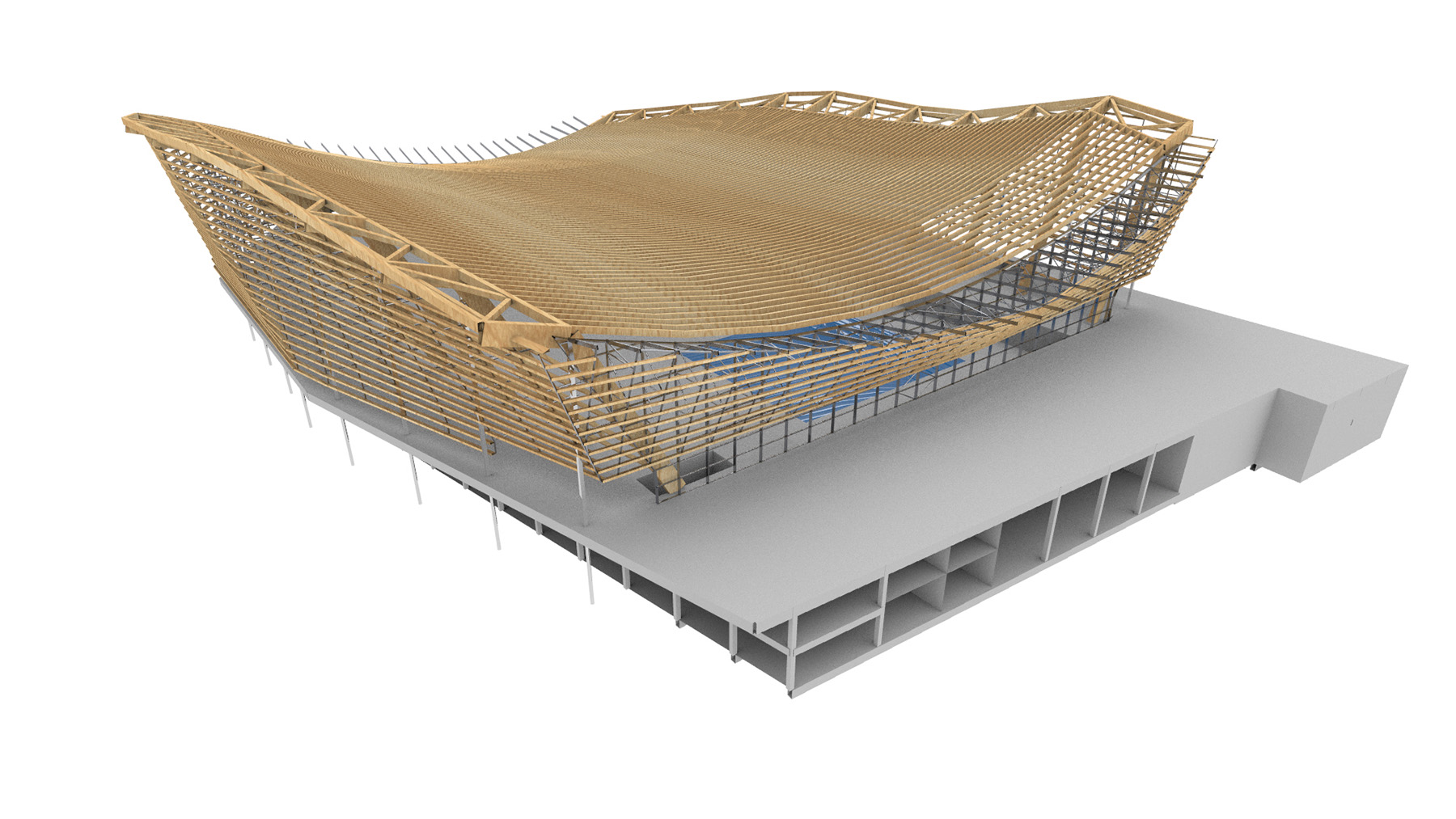
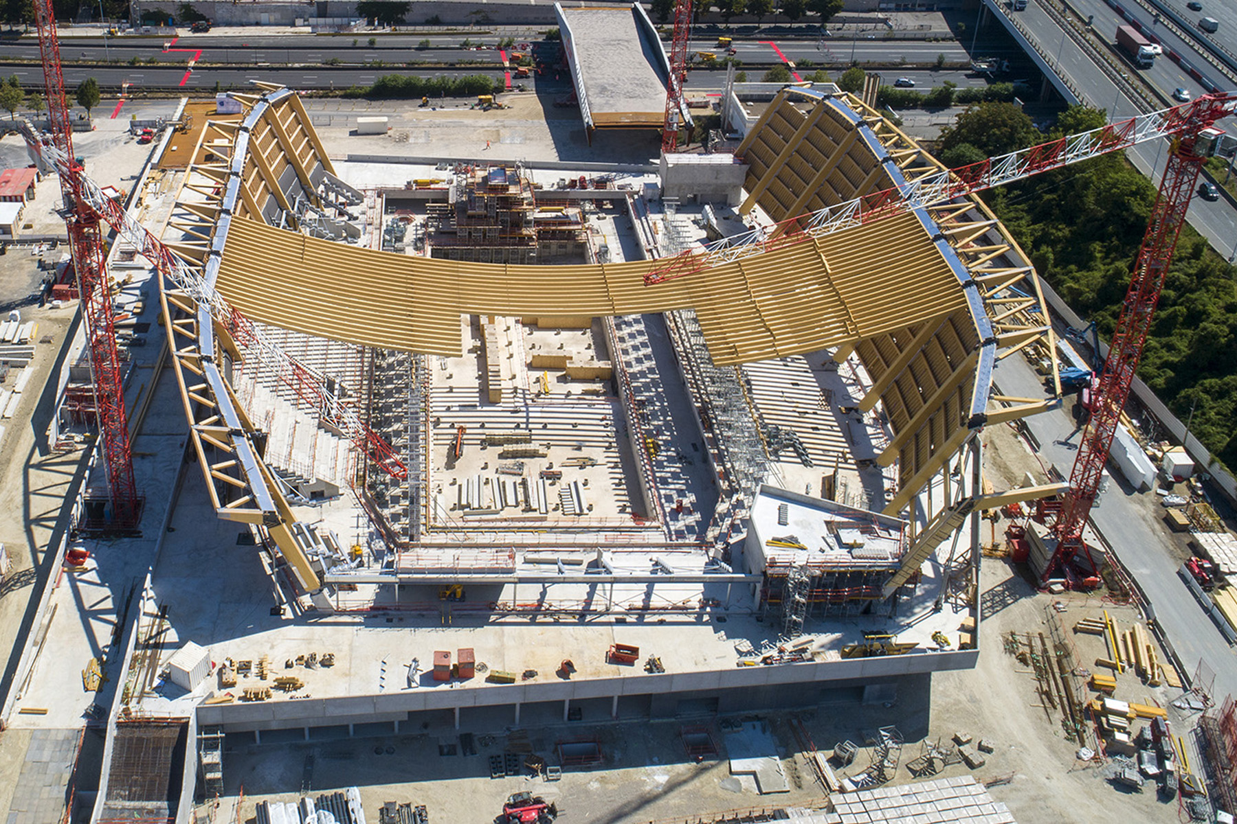
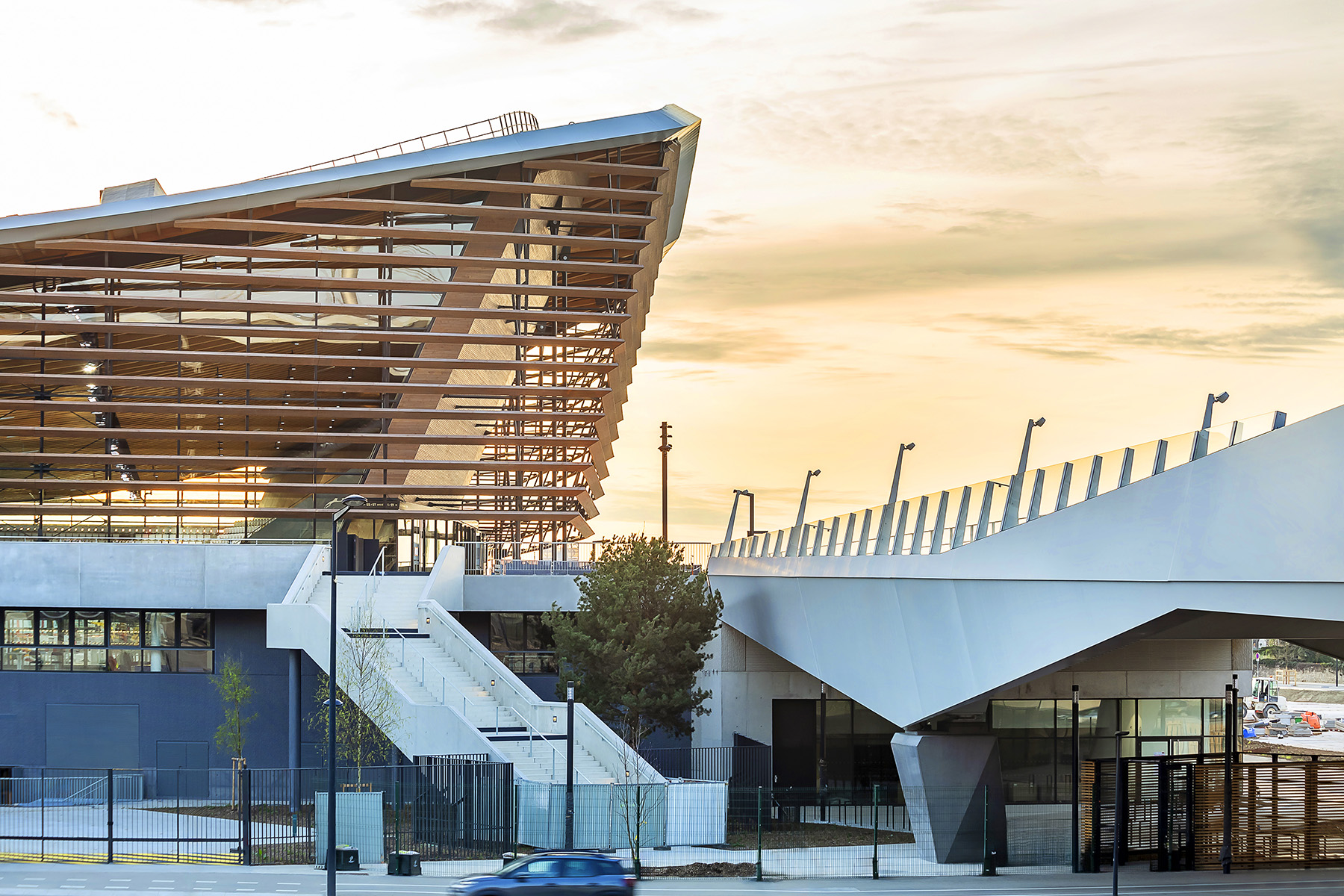
The superstructure is dominated by a unique catenary roof structure that features a wide-span, suspended-timber roof. Filigreed wooden tension elements are spaced at a constant 41 in. apart and reach a maximum span of approximately 295 ft across the pool.
Responsible design
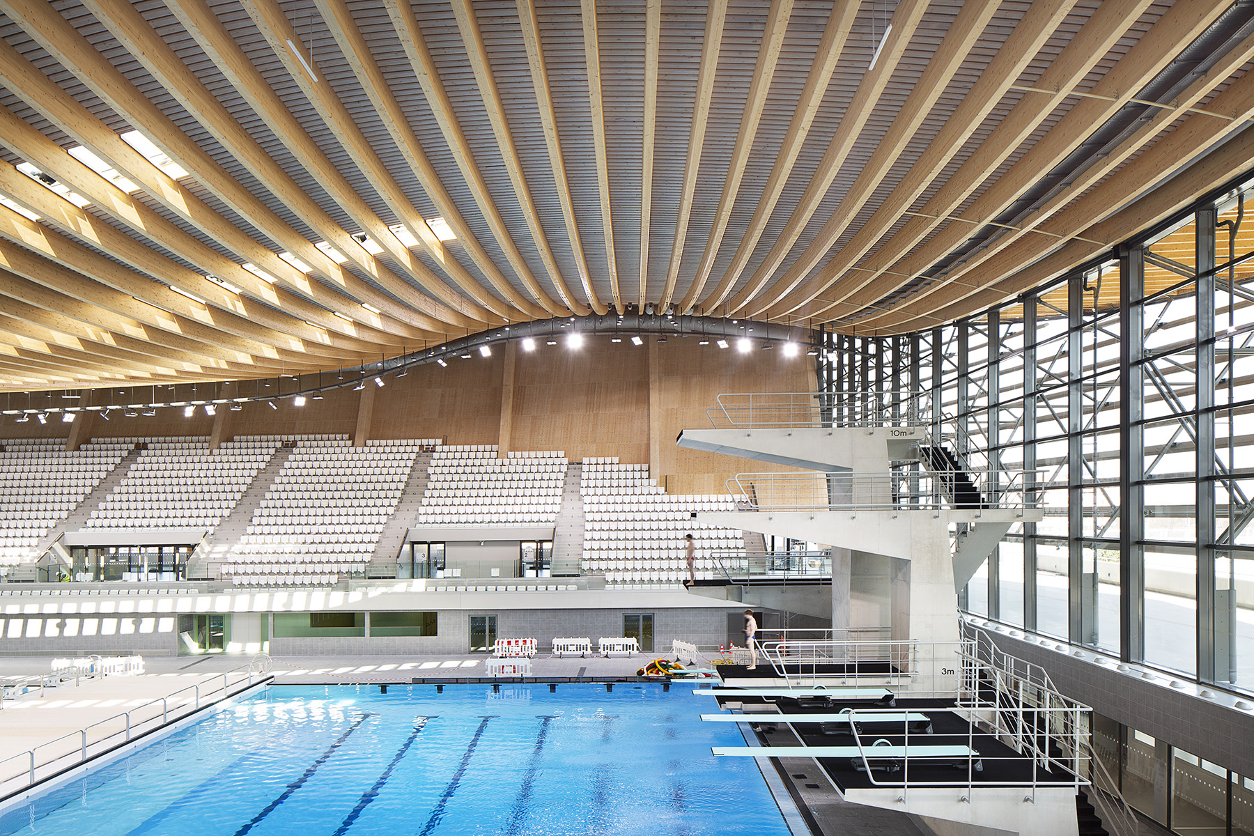
The indoor swimming pool features a floor area of about 107,640 sq ft that is covered by the timber roof structure. The main hall houses a pool that is 82 ft wide and 229 ft long, with one 50 m portion and another portion for diving, separated by a mobile partition wall. Thanks to multiple mobile partition walls and partially mobile pool floors, the 50 m portion can accommodate a variety of configurations.
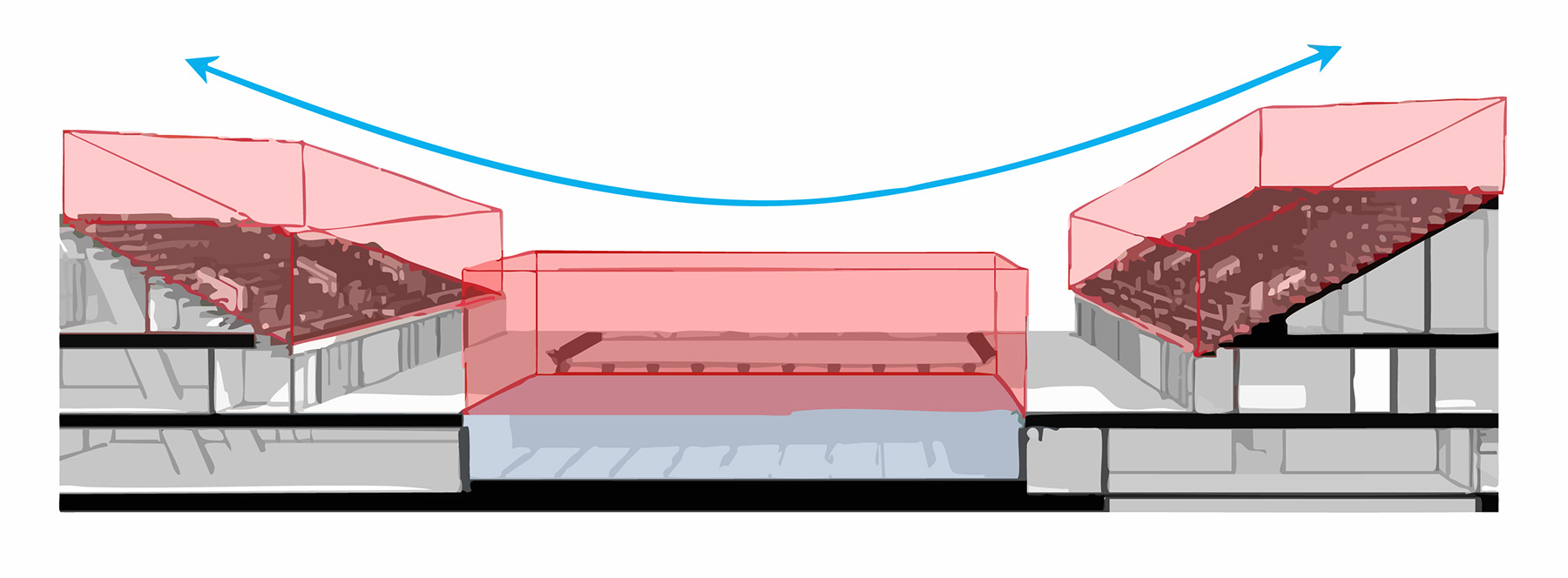
A key design consideration was how the roof could contribute to the project’s sustainability goals. This question led to two critical design features. First, the team designed the roof as a glue-laminated, or glulam, timber structure with a geometry that adapts to the usable area of the indoor swimming pool. The suspended, concave shape of the roof and the overall geometry come as close as possible to the required clearance profile of the building, grandstands, and diving tower. This reduced the volume of the hall by approximately 30%, leading to significant energy savings for heating.
Second, the use of a lightweight timber structure reduced and optimized the weight of the roof. Furthermore, it also reduced carbon emissions by approximately 2,000 tonnes. The design team analyzed all the building materials and the construction methodology to ensure the greatest possible contribution to the project’s sustainability goals. Strict carbon footprint and bio-sourced materials targets were monitored across all trades and throughout all design phases.
The wide-span roof structure is fitted with photovoltaic panels that make the facility one of the largest solar parks in France. The 53,819 sq ft of panels generate 25% of the sports facility’s total electricity requirements, which is equivalent to the annual power consumption of 200 households.
Material decisions
The design team used different species of wood in the Centre’s roof to help meet the project’s environmental requirements. For example, the team selected commonly available spruce glulam for all primary structural elements in the interior, such as columns, truss girders, and catenary elements, and it opted for Douglas fir for the exterior cladding due to its weather resistance.
Additionally, the design team chose steel for the connections between timber elements and for the external vertical tension tie-down bars that are exposed to weather conditions. Low-carbon concrete makes up a large part of the concrete substructure, which was subject to the demands of precasting and durability requirements. The roof above the timber catenary elements consists of wooden beams, a felt layer, a metal sheet, and foam glass integrated into membrane layers with a synthetic waterproof covering.
The total roof system — the connected buildup of structural, waterproofing, and insulation elements — allows the roof to behave as a stiff structural unit.
Tension and stiffness
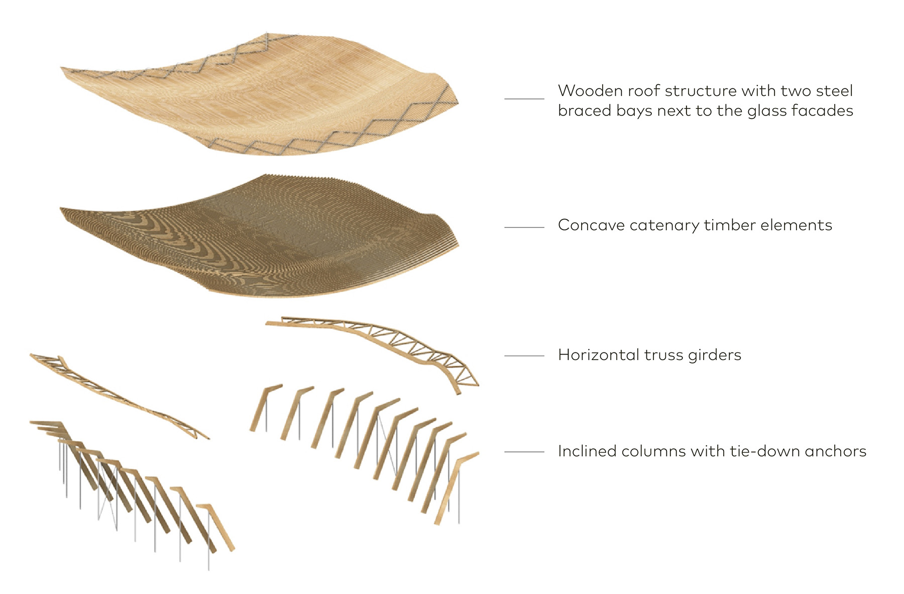
Tensile forces at the ends of the hanging timber elements in the roof structure are resolved through stiff horizontal truss girders that sit on each side of the roof edge. These girders, which vary in height between 9 ft and 29 ft, act as the load-collecting backbone for the roof structure and feature extremely low deformations.
The system achieves lateral stiffness through the force triangle of inclined columns in compression and vertical tie rods in tension, arranged at a 34 ft grid spacing. The architecturally robust inclined timber columns are protected within the pool’s enclosed volume, also called a pool envelope, while the visually lightweight steel tensile anchor rods resist external environmental conditions.
A centrally positioned longitudinal bracing system between the tension rods and the timber roof cladding, reinforced with steel strips in the gable area, completes the primary load-bearing structure.
The support points, each consisting of an inclined column and tension anchor, transfer the forces to the pile foundations via the concrete base. Two centrally arranged steel-braced bays provide lateral stability perpendicular to the catenary axis.
Suspension and sensitivity
Suspended roofs are highly efficient structures under equally redistributed loading. However, these structures react sensitively to asymmetrical loads and wind suction due to the extremely optimized cross sections of the tensile elements.
A detailed wind tunnel study helped the design team optimize the structure and ensure safety. This was especially true with respect to high-suction forces and, in some cases, the considerable asymmetrical loads that the design team analyzed when dimensioning the roof.
With a classic suspended roof made of lightweight steel ribbons, these loads would have required additional stabilizing bracing or additional ballast in the roof. But for the aquatics venue, the wide-span structure used timber elements with a larger section than would be necessary for a steel tension roof system. This provides the suspended structure with additional rigidity, enabling it to absorb any compression and bending stresses from these asymmetric loads.
In the case of suction loads on the roof structure, the forces in the load path were reversed. The suspended timber elements act as an arch structure, stabilized by the stiff wooden roof structure. The roof edges receive compression loads, which lead to a reversal in load direction in the inclined columns and vertical elements.
Roof geometry
The Centre features one of the longest-spanning timber catenary roof structures in the world. While the cross section of the timber elements is small, the overall dimensions of the roof structure are particularly impressive. The roof extends 374 ft in the longitudinal, or east-west direction, and 341 ft in the catenary, or north-south, direction.
The concave timber tension elements form the largest central part of the roof, while the cantilevered horizontal stiffening trusses on each side serve as canopies.
The variation in size of the timber cross sections, which spans from almost 10 ft to 30 ft, illustrates the different stress types and magnitudes each element is subject to. The roof columns have a large cross section of more than 23 in. by 59 in., while the horizontal truss girder edge beams exceed 15 in. by 59 in.
These large cross sections allow the elements to support the high-compression and buckling stresses that are introduced into these support elements, and, therefore, use a higher-capacity glulam.
In contrast, the hanging tension elements of the roof — measuring approximately 8 in. by 20 in. — appear delicate and emphasize the lightness of the roof even when using a more economical lower-strength glulam.
Another challenge was the variable geometry of the building envelope because the roof follows the exact minimum volume required and does not correspond to a linear shape.
The heights of the inclined columns vary along the longitudinal axis of the building and adapt to the clearance profile of the swimming pool hall. As a result, all 91 tension elements of the roof structure differ from one another in terms of shape, connection points, and curvature.
Manufacturing these beams to unique geometries and assembling them on-site as planned would have had a significant impact on the roof’s construction costs and production time. Therefore, the design team optimized the roof geometry before manufacturing, which it accomplished using the Rhino and Grasshopper software systems, both by Seattle-based Robert McNeel & Associates.
Calculation methods
One of the characteristics of a curved, concave geometry is that it requires nonlinear second-order calculations to consider large displacements. As mentioned previously, suspended structures are very efficient, and as a result, the force progression can be easily understood. However, because of their sensitivity, these structures react to boundary conditions such as support stiffness, detailing, and asymmetrical loads. Deformations can be quite large, both under gravitational loads and in the opposite direction under wind suction.
sbp conducted numerous sensitivity tests with various boundary parameters and investigated their effects on structural behavior. Among other analyses, the firm tested the following parameters and integrated them into the design:
- The stiffness of the concrete base where it meets the roof (columns and tie-back anchors).
- The stiffness of the pile foundations in the supporting soil.
- The stiffness of the connections at the bases and tops of the inclined columns.
Connection details
In addition to reviewing the forces generated at each connection, the team had to consider the stiffness and resulting global deformations for assembly. The connections between timber elements were fabricated as embedded steel knife plates, which meet at steel-to-steel connections, so that installation on-site was safe and quick using bolts or screws.
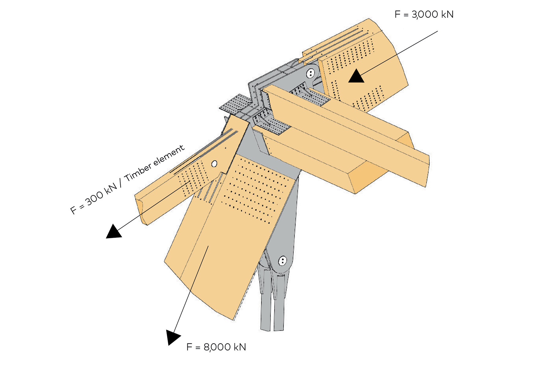
The largest connection detail was the four-tonne connection node of the primary loading elements between the horizontal truss girders and the supporting columns. It was installed in the column head at the factory, and the timber tension elements and tension tie-down bars were connected on-site to each column using bolts. The truss girder elements and connecting plates of the 10 timber tension elements were bolted together on-site.
The jointing between the wooden tension element segments alone was executed a total of 364 times. The steel knife plates installed in the factory were designed and optimized so that two dowel pins could be inserted at each connection point to transfer the forces and torques between the two elements.
Another important detail to finalize was the interface between the suspended timber roof and the independent glazed gable facades at the east and west elevations. These were designed as vertically independent structures, with the glazed gable facades supported directly on the concrete base and transferring horizontal wind loads to the Centre’s structure at the roof level only.
To cope with the high relative vertical deformations between the suspended roof and the stiff vertical facade, the team designed the connection detail so that the two structures are decoupled from each other vertically and horizontally parallel to the facade.
Detailing considered variable conditions such as the roof boarding and installation of the roof complex during placement of the glazed gable facades, resulting in different deformation statuses of the roof during construction and completion. During the installation process, the design team determined that a precise geometric survey, detailed installation calculations, and precisely fine-tuned adjustments were necessary to perfect the sliding connection detail.
Mathis SAS manufactured the timber beams and the standard connecting plates in the same facility. With the help of 5-axis CNC technology, the wooden components were manufactured with dimensional accuracy and the connection points precisely milled. All steel knife plates and large welded connection details were installed in the factory.
Impressive future
The project also included a pedestrian crossing that connects the Centre and Saint-Denis with the Stade de France, which is the country’s national stadium for sports and other events. The 328 ft long two-span bridge was designed and constructed with box girders at the edges of the walkway. Workers welded the bridge together on the side of the roadway and brought it into its final position using self-propelled modular transporters that traversed the highway. After the Olympics, the bridge walkway, originally 59 ft wide, was reduced to 39 ft by adding furniture and greenery.
When the project was unveiled, it quickly made a significant impression on athletes, architects, and the public. The hanging timber roof structure adds striking aesthetic appeal and also showcases remarkable material efficiency using bio-sourced and recycled materials.
Beyond its visual impact, the Centre Aquatique Olympique is celebrated for its responsible design, which prioritized sustainability and future use. Planners envisioned the facility as a community asset long after the Games concluded, transforming it into a public swimming pool that will serve residents of all ages. The Centre also offers teaching and wellness pools, and fitness facilities and a rock-climbing hall are to be added for public use by June 2025. This human-scale approach ensures that the facility will remain accessible, fostering a love for aquatic sports and promoting healthy lifestyles within its host community.
Michael Zimmermann, Dipl. Ing is managing director at schlaich bergermann partner’s Paris office. Andreas Pfadler, Dipl.Ing is associate director at schlaich bergermann partner’s Paris office.
Project credits
Client
Métropole du Grand Paris
Principal contractor
Bouygues Bâtiment, Ile-de-France, Paris
Architects
VenhoevenCS, Amsterdam,
and Ateliers 2/3/4/, Paris
Structural engineer
schlaich bergermann partner, Paris
Concession
Simbala (Récréa, Dalkia, and Omnes),
Guyancourt, France
Water treatment
Katene, Paris
Environmental consultant
Indigo, Paris
Mechanical, electrical, and plumbing
Inex, Montreuil, France
Timber construction
Mathis SAS, Muttersholtz, France
Timber facade
MTechbuild, Luçon, France
Facility operations
Récréa, Dalkia, and Bouygues Energies & Services, Seine-Saint-Denis, Paris
This article first appeared in the January/February 2025 issue of Civil Engineering as “The Olympics and Beyond.”

