By Leslie Nemo
New Orleans, which today hosts the sixth-largest water port in the United States, at one time handled the second-largest shipping volume in the nation. While at its peak, the port, located on one side of the Mississippi River, required cargo destined for local train lines on the other side of the river to be shuttled by ferry. The solution to this slow and dangerous transfer of goods was the Huey P. Long Bridge.
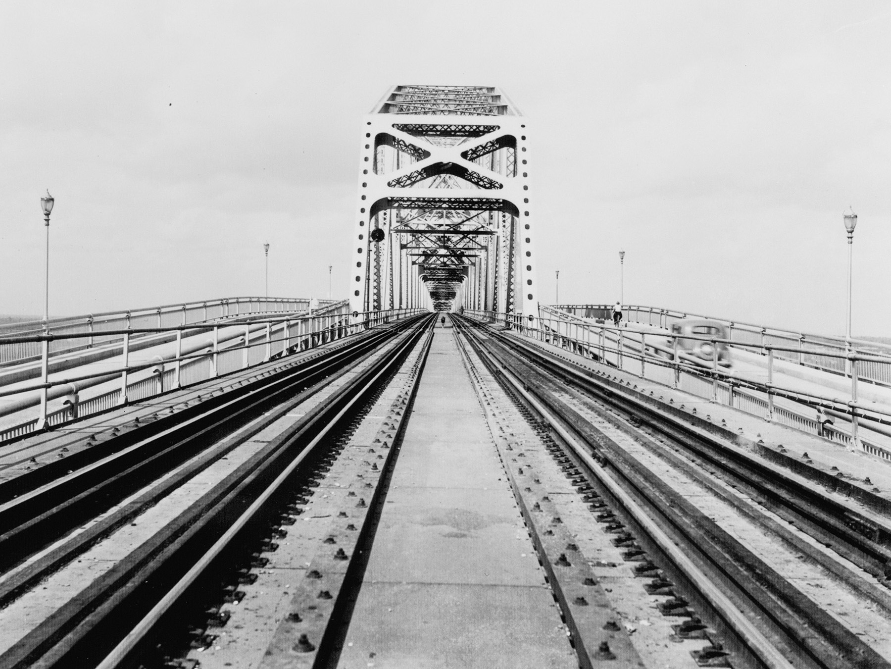
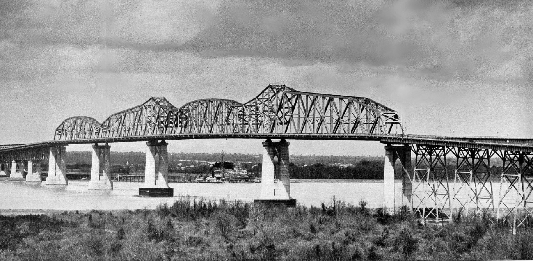
Opened in December 1935, the structure combines a highway with railroad tracks, the latter stretching about 22,995 ft and standing as the longest rail bridge of its type at the time. Construction managed to handle the speed and turbulence of the Mississippi River efficiently enough that the bridge was ready for traffic within three years. But just getting to the start of construction took decades, and it might not have happened at all without the help of a federal agency organized during the Great Depression.
In 1892, the Southern Pacific Railway proposed that a bridge replace the work that the ferries were doing around the port. Boat traffic had been ramping up and “the necessity for an improved crossing became daily more important,” wrote Frank M. Masters Sr. in Mississippi River Bridge at New Orleans, Louisiana — Final Report. Southern Pacific was one of many in the area connected to the docks themselves via the Public Belt Railroad, which was operated by the Public Belt Railroad Commission — the entity that would be responsible for constructing the bridge.
With some insistence from the Commission, the state passed a constitutional amendment in 1916 allowing New Orleans — via the Commission — to build and run infrastructure that would bring trains and vehicles across the river. Once this was passed, the Commission formed the Mississippi River Bridge Committee. This committee, guided by borings, soundings, and surveys, recommended a low-level, two-deck bridge with a vertical-lift central span, according to Mississippi River Railroad Crossing At New Orleans And Plan of Terminal Development. In 1921, another constitutional amendment allowed the city to raise $15 million in mortgage bonds to pay for the construction.
In 1924, the Commission asked Ralph Modjeski to draft a permit request to submit to the War Department. Having immigrated from Kraków, Poland, to the U.S. as a teen, Modjeski then left the U.S. to earn his civil engineering degree in Paris from the École nationale des ponts et chaussées (the National School of Bridges and Roads). He eventually returned to the U.S., working on about a dozen North American bridges before he joined the New Orleans-based project, according to the Historic American Engineering Record report “Huey P. Long Bridge” (HAER No. LA- 17). By this time, Modjeski had helmed his own firm for more than 30 years and had designed at least four bridges across the Mississippi.
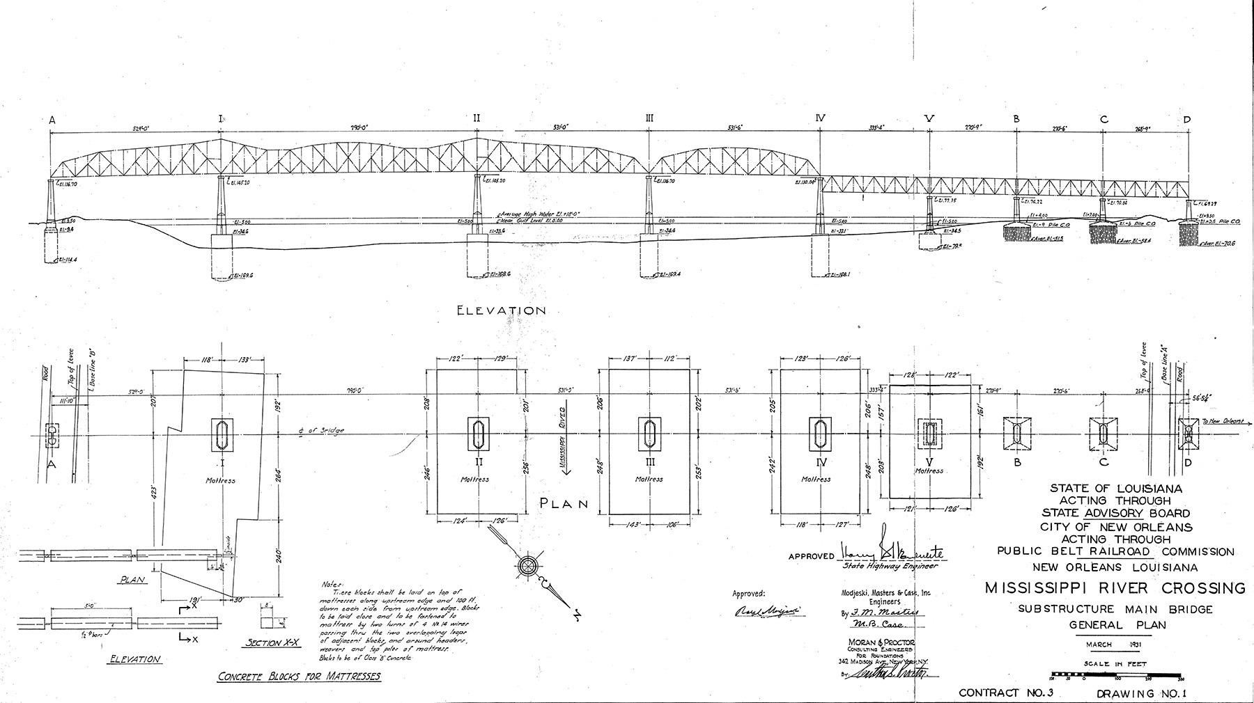
The Public Belt Railroad Commission and Modjeski proposed a low-level double-deck bridge: a roadway on the upper deck and two railway tracks on the lower deck, per Masters. However, the War Department rejected this proposal. Eventually a compromise was reached: “a cantilever bridge with 130-foot vertical clearance above Mean Gulf Level and a 750-foot horizontal span flanked on each side with 500-foot anchor arms,” according to Masters. The War Department approved the permit on June 11, 1925. However, the permit was revised once more in December 1930 when the federal agency required an additional 5 ft of vertical clearance.
Modjeski stayed on with the project to help prepare the design and oversee construction plans, though the workload eventually shifted to include the broader Modjeski, Masters, and Chase firm as the official engineer for the Public Belt Railroad Commission. Masters and Clement Edward Chase worked with Modjeski at young ages — Masters started when he was about 22, and Chase began when he was a college student. Both gained experience in other roles, and they eventually became partners with Modjeski by 1931. All three were members of ASCE.
In January 1926, the Southern Deep Well Drilling Co. performed new foundation borings. These samples provided additional information about the foundation on which the bridge’s piers would rest, as the 1918 borings had filled with too much silt and sand to be very insightful. The new samples went to Karl Terzaghi, Hon.M.ASCE, the father of soil mechanics, for analysis. Terzaghi concluded that the main piers should be “founded on a stratum of fine sand” 160-170 ft below Mean Gulf Level, according to Masters, ensuring the piers would bypass the “gumbo,” or higher clay layers, that would cause uneven settlement.
Bridge progress stalled over the next few years. The Commission, which needed banks and private rail companies to help finance the bridge’s construction and use, could not reach agreements over “motive power,” among other issues, said Masters. However, a new state constitutional amendment in 1928 removed this obstacle. Additionally, the authority to build the bridge expired that same year, forcing fresh negotiations with the War Department. Attempts to sell bonds fell flat after the 1929 financial crash, even when in 1931 the lowest bids for the construction contracts were significantly cheaper than expected at under $9.5 million.
However, the tide turned when the Reconstruction Finance Corp. bought the bonds. Established in 1932, the federal agency theoretically operated as a business, giving loans to enterprises like mining operations, banks, and railroads, though it often did not expect to recoup its losses. On Nov. 5, 1932, Southern Pacific agreed to rent the bridge once New Orleans and Louisiana built it. At the end of December, the Reconstruction Finance Corp. bought the state’s and the Commission’s bonds. The same day, four construction contracts were executed. The bridge was moving forward with $7 million in grants from the state and $6 million in bonds.
By the time the contracts were executed, officials and engineers involved in the bridge project were inundated with job applications and requests for employment from people around the U.S. desperate for work. Sen. Huey P. Long and Gov. O.K. Allen received direct appeals, while the various hotels the Modjeski, Masters, and Chase team stayed at in New Orleans received the bulk of the letters, according to the HAER report.
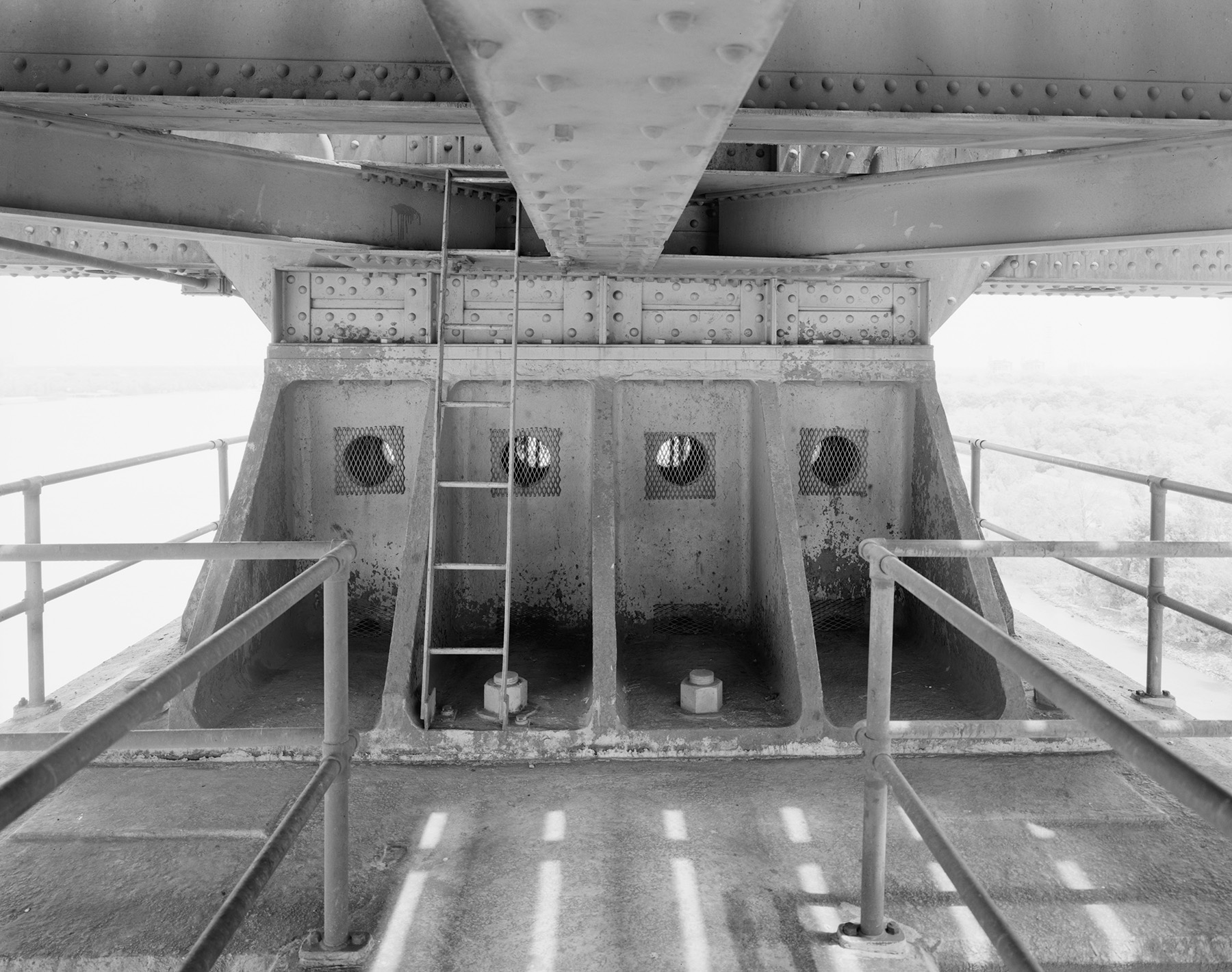
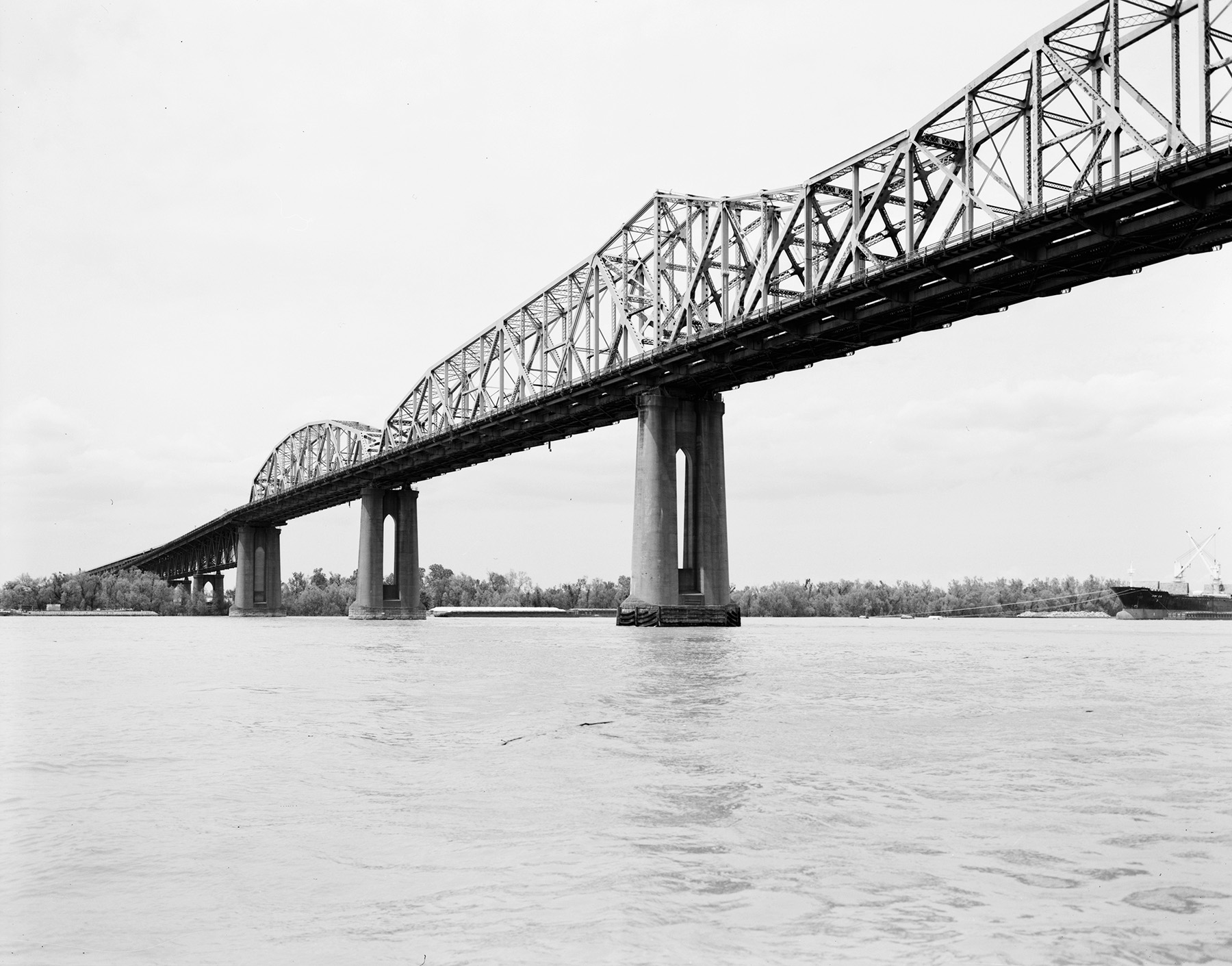
Though the bridge ran roughly north-south, the side New Orleans sits on became known as the “east” side and the opposite bank the “west” side. A total of nine piers support the bridge. Moving from east to west, the bridge comprises: four deck spans, a 528 ft through span, a 528 ft anchor arm, the main span, and another 528 ft anchor arm. The main span stretches 790 ft because of two 144 ft cantilever arms that frame a 502 ft suspended span.
Six piers — four in the river and one on each bank — needed caissons. In addition, five of the piers needed protective “mattresses” — made from willow sapling, brush, and wire weavings — to buffer water flow and mitigate scour. Lowering and placing the protective mattresses in the correct locations was challenging. Construction teams did not have much experience with rivers as strong as the Mississippi. Depending on depth, the current moved up to 6 ft per second. To sink the mattresses into place, workers on barges progressively loaded down the mattresses with “man size” stones, per Masters. Four of the five mattresses hit their target destinations within 15 ft; however, the mattress intended for pier I missed the mark, and a second mattress was needed at that spot.
Next came caisson construction. While the project engineers had a plan for how to build them, the team wrote bid descriptions that would let contractors propose their own methods for getting five of the caissons into the sand beneath the Mississippi. Siems-Helmers Inc., the firm that won the substructure main bridge contract, offered an approach, called the “sand island method,” which the group had pioneered for pier construction on the Benicia-Martinez Railroad Drawbridge in California, which was completed in 1930. The technique involved constructing a large sand pile or island, surrounded by a steel shell in which each pier would stand, and constructing the caisson on top.
Sand island assembly began with falsework construction. Workers drove piles in radial bents through the mattresses and into the riverbed, forming a falsework circle with an inner diameter equaling that of the sand island, according to Masters. Next came the confining shell for the sand island, which was made of sequential 10 ft tall steel plate rings. Workers assembled three of these rings at a time on needle beams before 12 hoist frames (located around the perimeter of the falsework) took the weight of the shell portion and lowered it by winches farther onto the same beams. Another trio of rings was assembled on top. Once all the ring layers were added, the mattress section lining the interior of each shell was dredged. Workers filled the structure with riverbed sand, using up to 35,000 cu yd for the larger islands.
Caisson construction began on top of the sand islands but only after the centerline of each pier had been triangulated. A steel cutting edge surrounded by wood forms filled with jet nozzles, caisson wall reinforcing, and smaller forms for 8 in. jetting wells allowed the first 20 ft of concrete to be placed. This enabled the cutting edge to settle evenly. Dredging sank the caisson until about 2 ft emerged above the sand island, when another 10 ft layer of concrete was placed on top.
Once 135 ft of caisson above the cutting edge had been assembled, workers paused dredging to add a 50 ft tall temporary cofferdam before the last portion of sinking broke through the clay gumbo, which fractured into big pieces when excavated. Sealing the caisson’s wells involved “one of the largest tremie concrete operations ever undertaken,” wrote Masters. In the end, the biggest positioning error happened at pier I, which was 0.96 ft east and 0.3 ft upstream of its planned position.
Using the cofferdam, workers installed granite masonry facing up to river level and then again at 25 ft above low-water level. The rest of the pier shaft was assembled via floating equipment. “A 100-foot-high steel derrick tower equipped on top with a stiff leg derrick was mounted on two barges rigidly framed together in a pair of steel trusses,” wrote Masters. Concrete was placed into adjustable steel forms and built up in 10 ft increments, each segment taking three days.
For piers I, II, III, and IV, all construction started and ended between June 1933 and November 1934, with pier IV finishing last after a blow-in caused water levels to rise high enough that portions of the cofferdam and the falsework were damaged, resulting in the steel shell of the sand island settling into an elliptical shape.
Bookending piers I-IV were pier A on the western side of the Mississippi and piers V, B, C, and D on the eastern shore. Land-based pier A was built using an open-dredge caisson “of conventional type, designed to be heavy for overcoming external friction,” according to Masters. The cutting edge was built on land in October 1933, and dredging began after the first two concrete lifts were assembled. A 150 ft tall guyed material tower was used to build the shaft. The work was completed May 15, 1934.
Pier V is closest to the New Orleans shoreline and sits at 80 ft below Mean Gulf Level. Workers built a miniature version of a sand island for this pier: a ring (108 ft in diameter) of steel sheet piles, instead of a steel shell, created the island’s borders. The falsework was also simpler than that built for the deeper piers. Begun in spring 1933, the shaft was finished in February 1934.
Piers B, C, and D — supporting three sequential 267 ft deck spans — were placed on nests of timber piles. Sheet piling served as a cofferdam, and once excavation started, cofferdam bracing was installed and supported by temporary piles. The piles also supported a runway for a traveling derrick for further excavation. The pattern of digging and placing new layers of bracing continued to 2 ft below the elevation of the footing base. Foundation piles were installed at varying depths depending on the pier. Concreting the shafts and placing backfill on top readied them for steel erection in late 1933 and early 1934.
Piers V, B, C, and D were the first to be completed, so bridge superstructure construction began at those locations in March 1934. The American Bridge Co. relied on guy derricks for the deck spans that connected these piers. Workers placed a derrick on pier V while other piles supported falsework beneath where the three 267 ft spans would go. While workers were trying to erect a second derrick, the anchorage for the first gave way — the bent supporting it did not have a mattress protecting against scour. In a change of plans, the second derrick was not constructed until the first was out of the reach of the barges supporting its engines.
Resting on skids on top of stringers on the railroad floor, the derrick moved forward, adding truss members in front of it and then turning to place truss members behind it. On its trek toward pier D, the derrick built the truss and top deck, and on the journey back, it assembled the highway cantilever bracket, girders, and deck members. Work on the deck spans concluded in August 1934.
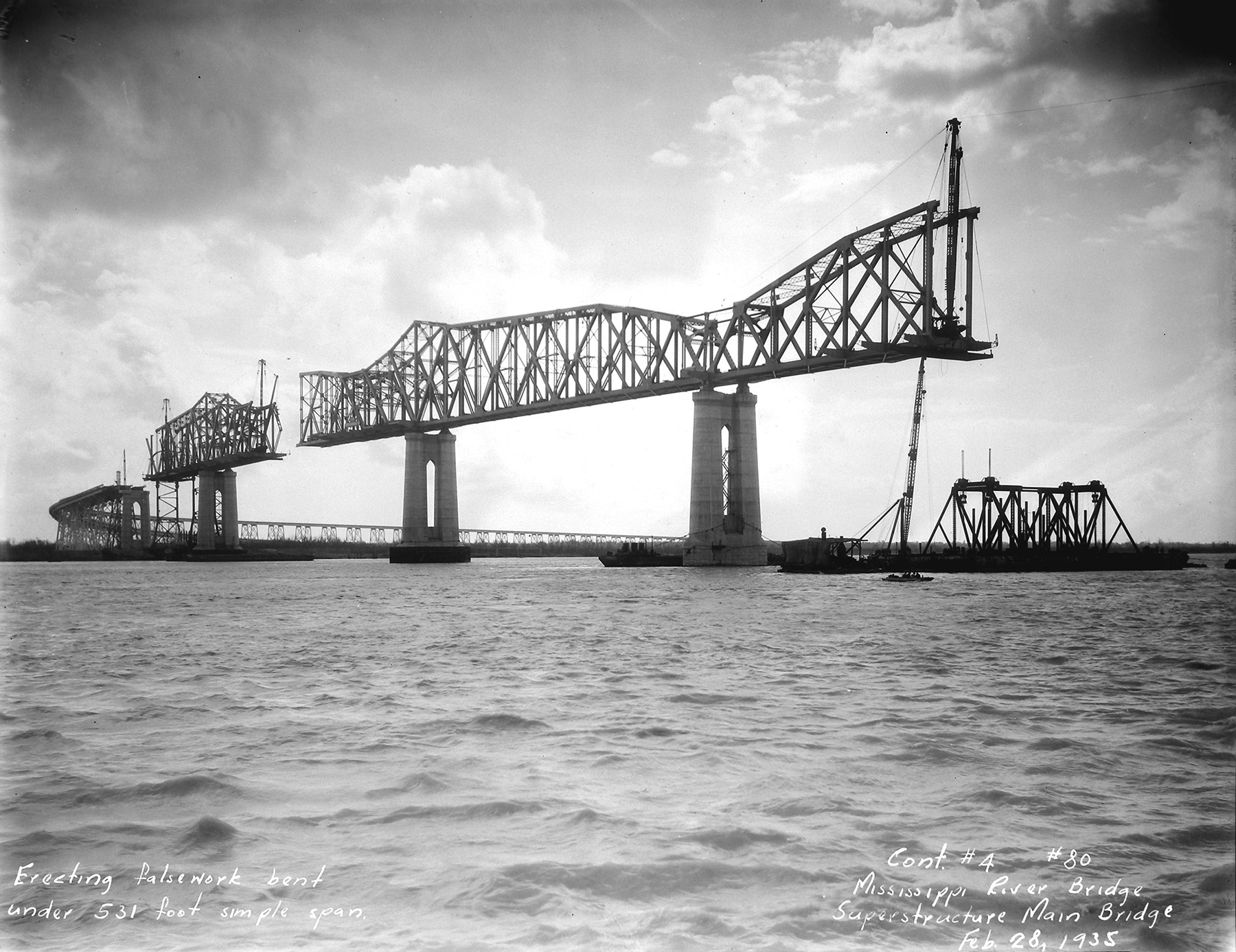
When piers II and III were finished on July 11, they became the basis for constructing the cantilever. A derrick was erected on pier II, guyed longitudinally to pier III and transversely to pier II thanks to a horizontal steel needle beam held to the concrete via anchor bolts. A steel bent of falsework was also installed into the river farther east.
The trusswork was erected via the balanced-cantilever method, a process developed by American Bridge Co. A second derrick on the bent allowed dual derricks to build the anchor and cantilever arms simultaneously. “The steel and erection loads on the anchor arm are always kept slightly greater than those on the cantilever arm, however, and the unbalanced portion of load is supported on the falsework bent,” according to Masters. The method was used to construct the eastern half of the cantilever structure. In December 1934, workers began applying the balanced-cantilever method to the other half of the cantilever structure, with the anchor arm connecting to pier A the following March.
Also during March, workers began building the 528 ft through span destined to connect pier III to pier IV. About half the span was cantilevered off the eastern anchor arm when the river rose, with the current too strong for installing falsework bents. Construction paused for more than three months for the water to recede during what became one of the longest periods of continued high water on record, according to Masters. Plus, one of the two 300-ton cages used to support the falsework tilted enough that work paused to level the structure and redrive its piles after the water level fell further in July. Once stable, the falsework allowed this section of construction to conclude by mid-September.
Two derricks working inward from piers IV and V completed the deck span over the last section of river crossing infrastructure in October.
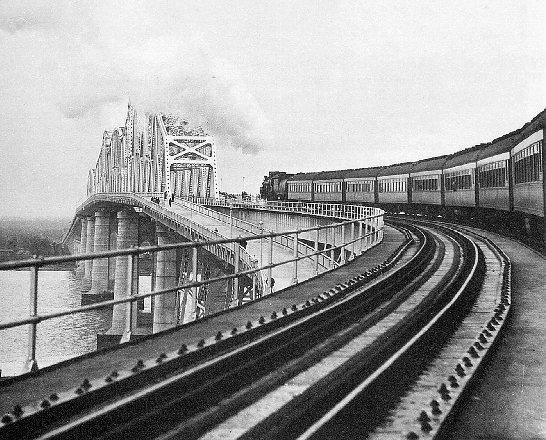
To debut the new bridge on Dec. 10, 1935, a 9:30 a.m. train carried about 1,000 passengers from the eastern side to the west and back again before celebrations ensued. Cutting the ribbon on the roadway was Rose Long, who had recently been widowed when her husband Huey was assassinated earlier in the year on Sept. 10. Prior to his roles as senator and governor of Louisiana, Long had been chair of the Public Belt Railroad Commission. Improving local transportation had been a key part of his campaign strategy for governor, and his strong political machine was the impetus behind the state constructing 9,800 mi of paved and gravel roads.
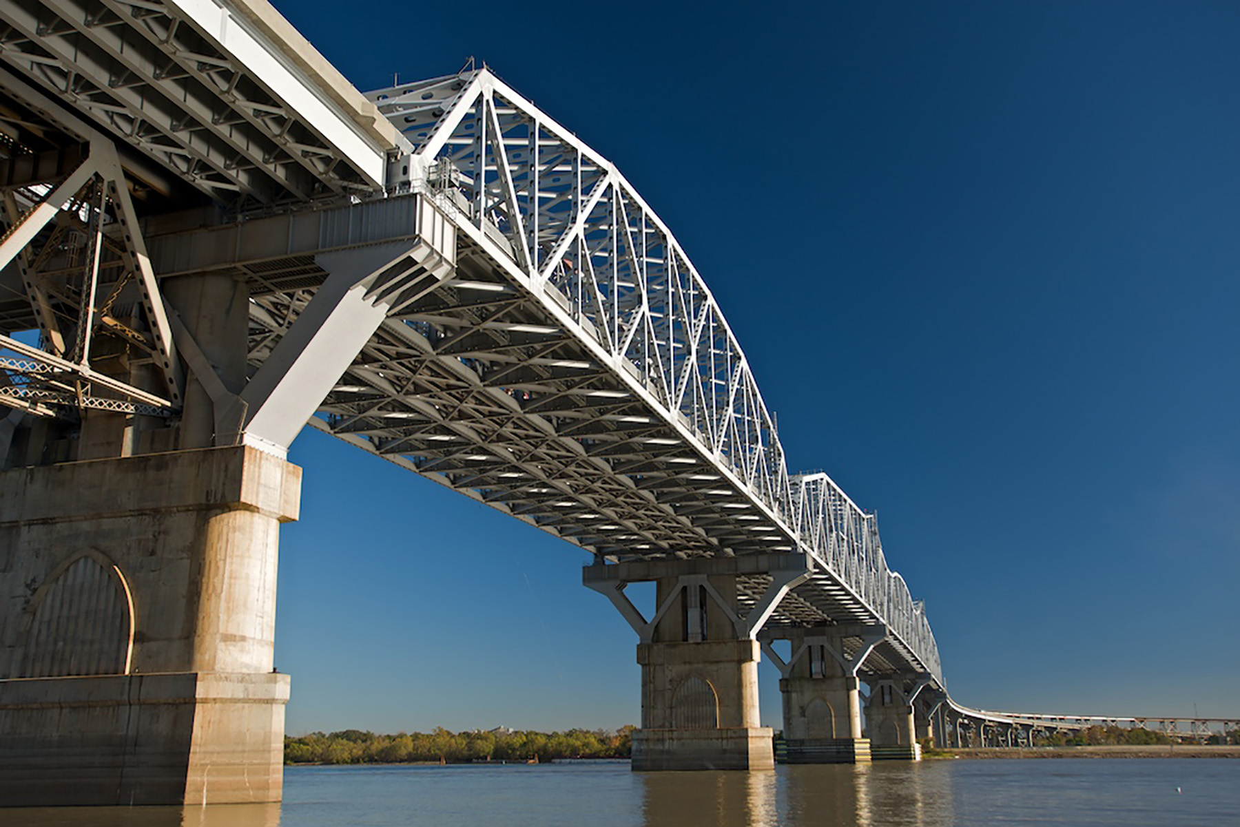
Just over 50 years after the structure opened, the Louisiana Department of Transportation and Development asked bridge engineering firm Modjeski and Masters to perform a feasibility study for widening the bridge. Design work proceeded through the early 2000s (the War Department might not exist anymore, but the U.S Coast Guard had to make its own approvals) and construction wrapped on the $1.2 billion widening project in 2013, a year after being designated a National Historic Civil Engineering Landmark.
Leslie Nemo is a journalist based in Brooklyn, New York, who writes about science, culture, and the environment.
This article first appeared in the September/October 2024 issue of Civil Engineering as “A Long Bridge for a Big Problem.”
